In the field (quick answer)
An HVAC system causes or spreads mold growth in three ways: water it makes (condensate that escapes the pan or drain), air it moves (leaky returns pulling damp attic or wall-cavity air), and surfaces it cools (ducts, boots and registers that sweat). In Central Texas, where the AC runs five or more months a year, a mold assessor should look at the visible HVAC parts and leave HVAC diagnosis and repair to a Texas-licensed air conditioning contractor.
By the end of this module you can:
- trace the air path and the water path of a typical Austin-area split system (an indoor unit and an outdoor unit joined by copper refrigerant lines), including a heat pump;
- name the three ways an HVAC system causes or spreads mold growth;
- tell which HVAC items belong in your assessment and protocol, and which belong to a licensed air conditioning contractor;
- work safely around an attic air handler.
The AC makes water, moves air and cools surfaces
Section 1.1 · about 7 min · then Check 1.1
Should a mold assessor inspect the HVAC system?
Yes, on most Central Texas jobs, because the air conditioner is often the moisture source, the delivery system, or both. Texas already expects it: under TDLR's training rules (16 TAC 78.68), the 40-hour mold assessment consultant course covers HVAC basics and the inspection, assessment and remediation of HVAC systems, and the mold assessment technician course covers HVAC systems and return and supply ducts.
The climate explains why. Austin's average July dew point sits around 70°F, and the normal high stays at 90°F or above from late May to late September. The dew point is the temperature at which the air's moisture starts to condense: any surface colder than that gets wet, like a glass of iced tea on a summer porch. Most thermo-hygrometers show it next to temperature and RH (Module 6 goes deeper). A home AC in a hot, humid month can pull 10 gallons or more of water out of the air in a single day, and all of it has to land in a pan and leave the house through a small plastic pipe.
While it runs, the system also pulls the house's air through itself over and over. If it draws from a damp wall cavity or a hot attic, it delivers that air to every room it serves. And it makes cold surfaces: the coil runs well below the dew point, and supply air leaves near 55°F, so supply ducts, boots (the metal box behind each ceiling register) and registers can drop below the dew point of the air around them.
Each of those three jobs (making water, moving air, cooling surfaces) fails in its own way and leaves its own mark. The rest of this module is about telling them apart.
How does a central AC system move air and water?
Picture a loop. Air leaves the rooms through a return grille, passes a filter, travels through the return plenum (the box or duct that feeds the unit), and passes through the blower and across the evaporator coil (which one comes first depends on the equipment; Module 2 shows the order for each type), then leaves through the supply plenum and the duct runs to each room's supply register. Then it comes back to the return and goes around again.
The water takes a one-way trip. Warm, humid air crosses the cold coil, and moisture condenses on its fins. That water drips into the primary drain pan under the coil and leaves through the primary condensate line, which usually runs outside, to a plumbing drain or to a condensate pump. A backup catches the water if the primary line clogs: a secondary drain pan under the unit, a secondary line (from the primary pan's overflow outlet or from the secondary pan), or a float switch that shuts the cooling off when water rises (the blower may keep running).
The one picture you need in your head: an attic air handler
Step through the loop the air takes, then the one-way trip the water takes. Then clog the drain and watch the backup work.
Notice that the air goes around and around, but the water only goes one way: out.
- The AC is often the moisture source, the delivery system, or both.
- In a hot, humid month it can pull 10 gallons or more of water a day; supply air leaves near 55°F.
- Air goes around in a loop. Water takes a one-way trip: coil, primary pan, primary line, out. Backup: secondary pan, secondary line, float switch.
- A little water in the primary pan right after a cooling cycle (seen with the power off) is normal.
In Austin, the system usually lies on its side in a very hot attic
Section 1.2 · about 7 min · then Check 1.2
Up next, after Check 1.1. Five quick questions lock in Section 1.1 before you move on. Answering questions right after you read helps it stick.
Where is the HVAC system in a Central Texas home?
In most Austin-area homes, the indoor equipment is in the attic, lying on its side (horizontal) on a platform. Closets and garages come next, where it usually stands upright (upflow), with air entering at the bottom and leaving at the top.
Most of those attics are vented (insulation on the attic floor, vents at the soffits and ridge). In a vented attic, the air can pass 130°F in August, so every leak, gap and thin spot of insulation on a system up there works against it. Some homes have a spray-foam (unvented) attic instead, with foam on the underside of the roof deck. That attic runs much closer to house temperature, but it is arguably worse for moisture: with no vents to dry it out, humidity can climb until its dew point is high enough to condense on ducts, boots, collars and the roof deck. Note which kind you're in, and take a temperature and RH reading there.
Know which of two kinds of equipment you're looking at, because the parts sit in different places:
- An air handler is one cabinet that holds both the blower and the coil, often with electric heat strips for winter. The coil and its drain pan are inside that cabinet.
- A gas furnace with a coil is two boxes: the furnace (blower, burners and a vent pipe that carries exhaust outdoors, metal on most furnaces and white plastic on high-efficiency ones; see Module 2) and a separate coil cabinet on top of an upflow furnace or beside a horizontal one. The drain pan lives in the coil cabinet, and the seam where the two boxes meet should be sealed. It's a common leak point.
Either one is the indoor half of a split system. The other half is the outdoor unit, or condenser: the fan box beside the house that holds the compressor, the pump that drives the cooling. Two copper refrigerant lines, the line set, run between the outdoor unit and the indoor coil; the larger one is wrapped in black foam insulation. A heat pump has the same layout, but its outdoor unit also heats in winter, usually with an air handler indoors. Leave the outdoor unit and the line set to the contractor; you just photograph the outdoor data plate.
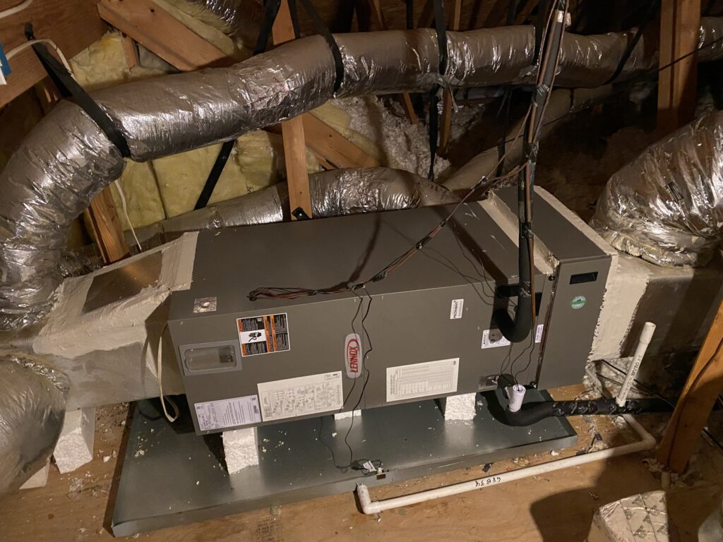
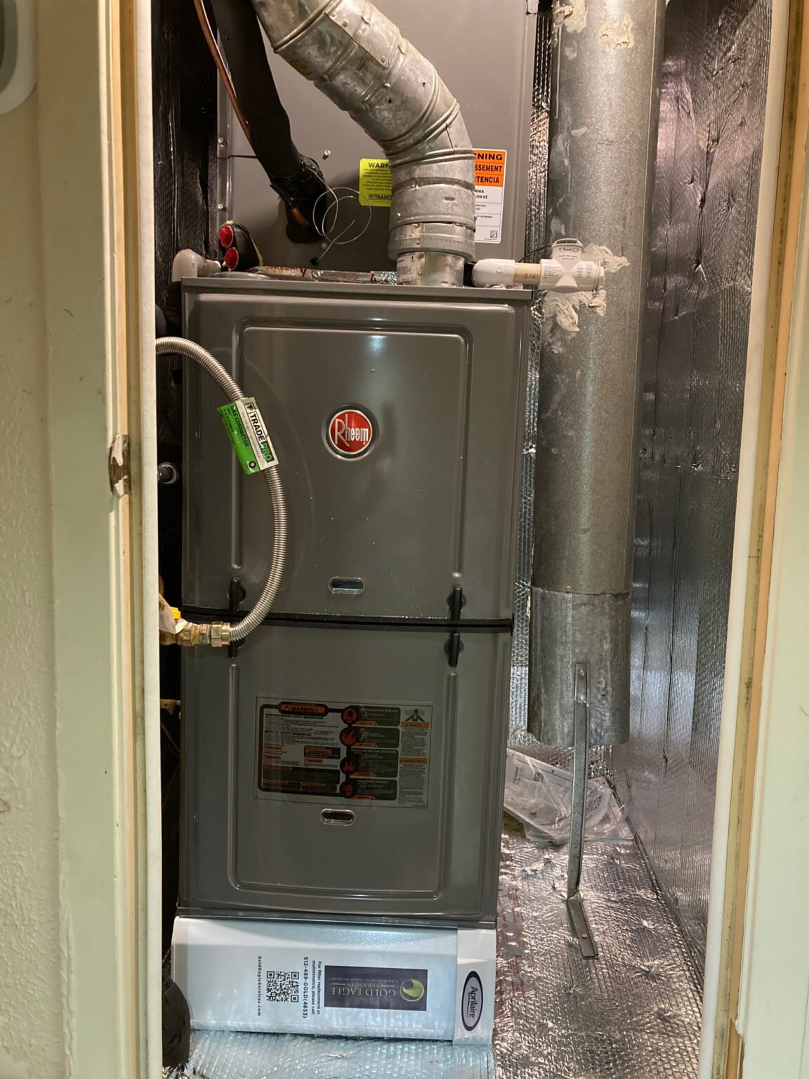
Module 2 walks through all four layouts part by part.
The ducts are rarely sheet metal. In most homes here, the plenums and trunk boxes are fiberglass ductboard, with flex duct (a wire coil wrapped in insulation and a plastic jacket) running to each room. Many homes have one or two central returns in a hallway ceiling, often with the filter right at the grille. Some older homes and closet installs use building cavities as return ducts (panned returns): a stud bay or a platform under the unit, lined with sheet metal or ductboard, or sometimes nothing at all.
- Most indoor units here are in the attic, horizontal, on a platform; closets and garages come next (upflow).
- Vented attic air can pass 130°F in August. A spray-foam attic runs near house temperature, but humidity can build up in it and condense on ducts, boots and the roof deck, which makes it arguably worse for moisture.
- Air handler: blower, coil and pan in one cabinet. Gas furnace with a coil: the pan lives in the separate coil cabinet.
- Ducts: fiberglass ductboard plenums with flex duct runs; some homes use building cavities as returns.
Most HVAC mold problems are water, air or a cold surface
Section 1.3 · about 7 min · then Check 1.3
Up next, after Check 1.2. Lock in where the system lives before you learn how it fails.
What HVAC problems cause mold?
Most HVAC-related mold problems you'll document fit one of three patterns: water the system makes, air the system moves, and surfaces the system cools. Every later module in this course builds on one of them.
1. Water the system makes
Condensate stays in the house when the drain path fails. Culprits include clogged primary lines, pans that rust through, missing traps, secondary pans that fill and overflow onto ceiling drywall, and float switches that are missing, mounted wrong or bypassed. Look for: stains on the ceiling below the air handler, rust lines in the pans, slime in the drain line, water marks on the platform, and a secondary line dripping at the soffit or over a window (a sign the primary is blocked). The EPA lists poorly draining condensate pans in air handlers among the common hiding places for mold.
2. Air the system moves
Air leaks are the most underrated part of an HVAC mold investigation. Leaky returns, unsealed return plenums and panned returns pull air from attics and wall cavities into the system, and leaky supply connections push conditioned air out and pull humid air in somewhere else. The collars, where each flex run attaches to the plenum and to the register boot, are among the most common duct leak points, so look closely around every one you can reach. Rooms with the door closed and no return path push air out through gaps in the walls, while the rest of the house is pulled negative and draws hot, humid air in through its own gaps. Static pressure, the resistance the blower works against, makes all of this worse when it runs high (too few returns, a restrictive filter, crushed flex, closed vents). Look for: dirt lines on carpet edges and around return grilles, dust trails around collars and duct seams, and return grilles mounted over unsealed openings. Module 4 covers collars, and Module 5 covers static pressure and air leaks.
3. Surfaces the system cools
Supply ducts with torn or compressed insulation, uninsulated boots, boots not sealed to the drywall (which let hot attic air reach the cold register), and registers in humid rooms all sweat, and low airflow across the coil (a clogged filter or dirty coil) makes the supply air colder, so they sweat more. A crushed flex run mostly starves its own room, and that room's boot and register can sweat from the slow air. Look for: drip marks or stained drywall around ceiling registers, wet insulation under supply boots, rust on register louvers, and mold rings on the drywall around a supply outlet.
Many jobs show more than one pattern
An oversized system, for example, tends to short-cycle: it runs in brief bursts that cool the air quickly but shut off before the coil has pulled much moisture out. With the fan set to ON, water left on the coil evaporates back into the house. Either way indoor humidity stays high, so every cold surface in the house sweats more readily. Module 6 covers it.
- Three patterns: water the system makes, air it moves, surfaces it cools.
- A secondary line dripping at the soffit or over a window is a sign the primary is blocked.
- Air leaks are the most underrated part; collars are among the most common duct leak points.
- Low airflow across the coil makes supply air colder, so cold surfaces sweat more.
You look, photograph and measure. The ACR contractor diagnoses and fixes.
Section 1.4 · about 9 min · then Check 1.4
Up next, after Check 1.3. Three patterns, five questions. Then the part that keeps you in your lane and off the ceiling drywall.
What HVAC checks fit inside a Texas mold assessment?
Look, photograph and measure with your own instruments; leave HVAC diagnosis and repair to a Texas-licensed air conditioning contractor (TDLR Air Conditioning and Refrigeration, or ACR, license). Your license covers mold assessment, not HVAC service or repair, and Texas mold law (Occupations Code ch. 1958) doesn't cover HVAC or duct diagnosis, repair, cleaning or replacement that isn't done for mold assessment or remediation. Mold growing on HVAC parts is different: it goes in your protocol like any other affected material, and the moisture cause goes to the ACR contractor. Where the line falls on a typical attic system:
| Inside your assessment | Belongs to the HVAC contractor |
|---|---|
| Looking at what's visible: grilles, filter, pans, drain line, duct jackets, the line set, the attic platform | Touching the refrigerant circuit: gauges, line sets, brazed joints |
| With the power off, removing the filter, or a blower or coil access panel held by screws alone (and no drain or refrigerant line through it). Look and photograph; don't reach inside. If a panel also covers heat strips, a breaker or the incoming power wiring (on many air handlers one panel covers it all), it is the electrical compartment: leave it on (Module 2). A furnace blower door that lifts off on tabs or latches, or has a door switch, stays on: note the data plate as not accessible. Never open the burner compartment. | Opening the electrical or control compartment or a furnace's burner compartment, testing controls or capacitors |
| Photographing the indoor and outdoor data plates (model and serial numbers) for your notes. If you can't reach a plate within these rules, write "indoor data plate not accessible" | Decoding age and size, measuring static pressure or airflow, and diagnosing what's wrong |
| Moisture readings, surface temperatures and photos with your own instruments | Clearing drain lines, resetting or moving float switches, sealing ducts |
| Sampling as your assessment plan calls for (record whether the system and blower were running during each air sample, and the fan setting) | Deciding whether the system is sized right, or whether it needs repair or replacement |
| Writing mold-affected HVAC parts (pans, coil, ductboard, flex) into your protocol and clearance criteria | Fixing the moisture source so the growth doesn't come back |
| Writing "evaluate and correct by a Texas-licensed ACR contractor" (no company named) | Doing that evaluation and correction |
On foil duct jackets and ductboard, take surface temperatures with a contact probe (foil skews pinless moisture meters, pins puncture it, and shiny foil fools IR thermometers) and compare them with the dew point your hygrometer shows for the air around them. Take moisture readings on the drywall, wood and insulation around them.
Say what you see
Writing down what you see is your job. Explaining why it happened is often the contractor's. Name the finding precisely and leave the diagnosis to the right license: "Secondary drain pan holds about 1 inch of standing water; ceiling drywall below is stained" beats "Drain is clogged."
How do you work safely around an attic air handler?
An attic air handler puts you on a ladder and a narrow platform, beside live wiring, in air that can pass 130°F. Work in this order: checks that need the system running come first, then you shut it down for panel work.
Step 1: Before you go up
- If you smell gas, don't touch any switch, thermostat or breaker, since a spark can ignite it. Get everyone out of the house and call 911 from outside.
- Record how the system was running when you arrived: thermostat mode, setpoint, fan setting (AUTO or ON), and whether it's running. Shutting it off erases that evidence.
- If it was off when you arrived, ask why before you turn it on, and get the owner's OK. Don't start it if someone shut it off on purpose (a tag, a note or containment), if you smell gas or something burning, or if you see visible growth at a grille or the filter. Before you start it, go up and look at the secondary pan (and the ceiling below the unit): if the pan holds water, leave the system off and note it. If you already suspect growth in the unit or ducts, weigh whether running it fits your sampling plan, since it can spread spores through the house.
- Do the running-system checks next, with the system cooling: run times (Module 6), tissue and door tests (Module 5), temperature and humidity readings, and flow at the drain's end (Module 3). Record whether the system ran during each air sample.
- Wear your PPE: gloves, eye protection and the respirator your mold safety program calls for when you open a cabinet, pull a filter, or work near suspected growth, loose fiberglass or rodent droppings. Lift a filter out gently, since a loaded filter sheds what it caught, and if your plan calls for sampling the filter, take a tape lift or swab from it, then put the same filter back. Don't sweep or stir droppings.
- Set the attic ladder up fully unfolded, feet flat, hinges tight, and rated for your weight with your gear. Keep three points of contact, and carry tools in a bag or on a belt.
- Plan for the heat. From late May to late September, schedule attic work for the morning, keep trips short and carry water. Tell someone on site you're going up, and come down at the first sign of dizziness, cramps or confusion.
Step 2: Shutting down
- Tell the occupant before you shut down a running system.
- Turn the system off at the thermostat, then at the service switch (a light switch, a pull-out disconnect or a breaker on the indoor unit's own cabinet). An air handler with heat strips often has two breakers on its cabinet, fed by separate circuits; turn off every one. The disconnect beside the outdoor unit does not cut power to the indoor unit.
- Confirm the blower has stopped and doesn't restart. On a furnace, a status light seen through the blower door's small window, if it has one, goes dark.
- If you can't find a switch at the unit or can't confirm the power is off, leave the panels on. Gas furnaces normally have a safety switch on the blower door (a button that cuts power when the door comes off), but air handlers often don't, so never count on one. A motor capacitor can hold a charge after the power is off.
- If the system has a UV lamp, make sure it's off before you look into the coil area. Signs of one: a small housing or power box on the plenum or cabinet, a violet glow at a viewing port, a warning label, or a cord running to a separate outlet. Many stay on when the unit's switch is off. With the owner's OK, unplug it; if you can't confirm it's off, leave that panel on. UV-C light burns eyes and skin, so never look at a lit lamp, and don't touch the lamp itself (most contain mercury).
Step 3: While you're in there
- Never open the electrical or control compartment or a gas furnace's burner compartment, and leave the refrigerant lines and the furnace vent pipe alone. Don't cut tape or mastic sealing a panel; photograph it and note it instead.
- Stay on the joists or decking. Insulation hides joists, wiring and junction boxes, so step only where you can see framing or decking, and watch your head for roofing nails poking through the deck. A foot through the ceiling damages the very drywall you may be there to document. Don't step on ductboard or flex; it crushes and tears.
- Never run the system with a panel off or the filter out.
Step 4: Leaving it as you found it
- Put back what you took off, in the same orientation.
- Return the system to the state you found it (service switch, thermostat mode, setpoint and fan setting as recorded), and note it in your report.
- If you found a safety concern (gas odor, scorching, a burning smell, active overflow), leave the system off, tell the owner in person and in writing, and note it.
- You look, photograph and measure. Decoding data plates, static pressure, clearing drains and sealing ducts belong to the ACR contractor.
- On foil jackets and ductboard: surface temperature with a contact probe; moisture readings on the materials around them.
- Write the finding precisely, plus "evaluate and correct by a Texas-licensed ACR contractor" (no company named).
- Record how it was running first. Shut down at the thermostat, then the service switch; the outdoor disconnect does not cut power to the indoor unit.
Wrap-up
A little water in the primary pan right after a cooling cycle is normal.
You didn't make a prediction at the top. That's fine.
The coil runs well below the dew point, so moisture condenses on its fins and drips into the primary drain pan. That is the system doing its job, and you see it with the power off, right after the system has been cooling. The finding is standing water that stays long after shutdown, rust, slime, a wet secondary pan, or water anywhere outside the pans.
Field project: your Module 1 checklist
Take it on your next job. Your checkmarks are saved on this device.
How we know this
- TDLR mold training rules, 16 TAC 78.68 (assessment consultant and technician course content).
- Texas Occupations Code ch. 1958 (mold assessors and remediators) and 16 TAC ch. 78.
- U.S. EPA Mold Course, Chapter 2, which lists poorly draining condensate pans in air handling units among the places hidden mold grows: EPA Mold Course, Chapter 2.
The air handler and the furnace, part by part
The four layouts you'll meet (attic and closet, air handler and furnace with coil), where each part sits, and which panels are safe to open with the power off.
Start Module 2 →In the field (quick answer)
A Central Texas indoor unit is either an air handler, where the blower and cooling coil share one cabinet (often with electric heat strips), or a gas furnace with the coil in a separate cabinet on its supply side. Each comes horizontal in attics or upflow in closets, so the coil, pans, filter and leak points move with the layout. Name the layout first, photograph the data plates, and with the power off open only three panels: the filter door and the screws-only blower and coil access panels (no tape or mastic over them), looking without reaching in.
By the end of this module you can:
- tell an air handler from a gas furnace with a separate coil at a glance;
- find the blower, coil, pans, filter, plenums, drain connections and heat source on the four common layouts;
- say which way air moves through each one, and where its seams leak;
- know which panels you may remove with the power off, and which you never open;
- explain static pressure in plain words.
An air handler is one cabinet. A gas furnace with a coil is two.
Section 2.1 · about 6 min · then Check 2.1
Why does it matter which one you're looking at?
Because the parts you care about move. On an air handler, the cooling coil, its drain pan and the blower share one cabinet. On a gas furnace system, the coil and its pan live in a separate coil cabinet attached to the furnace. Look for the pan in the wrong box and you'll miss it.
Each kind comes two ways: lying on its side in the attic (horizontal) or standing upright in a closet or garage (upflow). That makes four layouts. Name the layout before you touch anything, and the rest of the inspection falls into place.
How do you tell them apart at a glance?
Look for a vent pipe and a gas line, and make sure both connect to the unit's own cabinet. A gas furnace has both: a flue (vent) pipe that carries exhaust outdoors, and a gas pipe with a shutoff valve. An air handler runs on electricity alone. Its heat, if it has any, comes from electric heat strips inside the cabinet (the main heat on a cooling-only system, backup heat on a heat pump), and the breakers for those strips often poke through the front panel.
Trace the pipe to where it ends
In a garage or closet, a gas water heater's vent pipe and gas line often run right beside an air handler. A pipe that passes the cabinet isn't the cabinet's pipe. Follow each one with your eyes until it ends: at the unit, it's a furnace; at the water heater, it isn't.
A high-efficiency (condensing) gas furnace vents through white plastic pipe, through the roof or out a side wall, instead of a metal pipe. The gas line is still there. It also makes its own water when it heats, so it adds a second drain to trace.
Where do the parts sit in each one?
- Air handler: one cabinet holds the coil, the primary drain pan and the blower, with any heat strips near the supply outlet.
- Gas furnace with a coil: the furnace holds the blower, the burners and the heat exchanger (the metal chamber that passes burner heat to the air while keeping the exhaust separate). The coil and its primary pan sit in the separate cabinet on the supply side: on top in a closet, beside it in an attic. The joint between them, the coil-to-furnace seam, should be sealed, and it's one of the first places to look.
In summer the furnace's burners stay off, but its blower still runs the air conditioning, pushing air through the coil.
Cutaway: where the parts and the pan sit
Pick the equipment and the layout, then step through the parts in the order the air meets them. Watch where the primary pan goes.
Which way does the air move through each one?
On every layout, air enters the return side, passes the filter and leaves the supply side. What changes is the order of the coil and the blower, and that decides whether the coil and its pan sit under suction or under pressure. Think of a shop vacuum and a leaf blower: one pulls air through, the other pushes it.
- Most air handlers are draw-through: the blower sits after the coil and pulls air through it, like the shop vacuum. The coil and pan are under suction.
- A coil on a gas furnace is blow-through: the furnace blower pushes air through the heat exchanger and then the coil, like the leaf blower. The coil, its pan and the coil-to-furnace seam are under pressure, so a gap there pushes house air out rather than pulling attic air in. The seam comes before the coil, so air leaking there hasn't been cooled yet: it's house-temperature air in summer and furnace-heated air in winter. Only the coil cabinet after the coil, the supply plenum and its collars leak cooled air.
That's why drain traps matter. On a draw-through unit, an untrapped drain or an open cleanout lets the blower suck air up the drain line, which can hold water in the pan until it overflows. On a blow-through coil, an open drain blows conditioned air out instead. Trap requirements come from the manufacturer's instructions, so simply note whether a trap is there. Some open tees on a drain line are meant to be open vents and some are cleanouts missing a cap; photograph any open tee and let the ACR contractor judge. Module 3 follows the drain from there.
- Air handler: one cabinet holds the coil, primary pan and blower, with heat strips near the supply outlet.
- Gas furnace with a coil: the furnace holds the blower and burners; the coil and its pan sit in a separate cabinet on the supply side, joined at the coil-to-furnace seam.
- A vent pipe and a gas line that both connect to the unit's own cabinet mean a furnace. Trace them, because a water heater's pipes can sit right beside an air handler.
- Draw-through (most air handlers): coil under suction. Blow-through (coil on a furnace): coil under pressure. Note whether the drain has a trap.
The layout decides where the pan, the filter and the leaks are
Section 2.2 · about 8 min · then Check 2.2
Up next, after Check 2.1. Five quick questions on Section 2.1 first. Answering questions right after you read helps it stick.
Four layouts cover nearly every home you'll walk into. For each, here's how to recognize it, where the parts are from the return end to the supply end, and where its seams leak. Dust lines at a seam (a dark streak along a joint) show air moving through it.
What does a horizontal air handler in an attic look like?
A long metal box lying on its side on a platform, with a ductboard return plenum at one end, a ductboard supply plenum at the other, and flex runs leaving the supply plenum's collars. No vent pipe, no gas line.
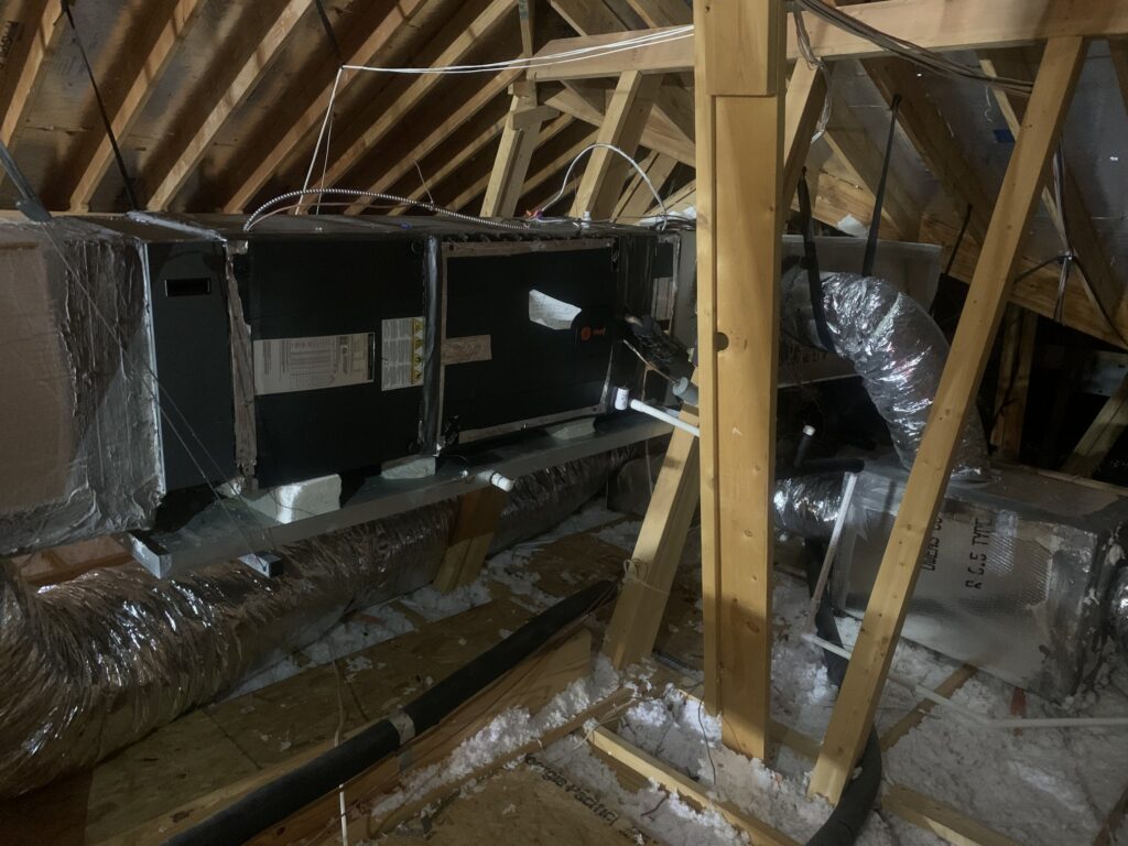
- Filter: at a hallway ceiling return grille, in a slot (filter rack) at the unit's return end, or in a thick media filter cabinet beside it.
- Coil and primary pan: near the return end. The drain connections leave the side of the cabinet: a lower primary port and often a higher secondary port, each piped to its own line or capped.
- Blower: after the coil, behind the blower access panel.
- Heat strips: near the supply outlet, behind the electrical section.
- Secondary pan: under the whole cabinet, with its own drain line or a float switch.
- Cabinet liner: the insulation lining the inside of the cabinet is often fiberglass, which may be bare (exposed and porous) or foil-faced; some cabinets use foam. Note which you see (Module 7).
Where it leaks: the return plenum joint (under suction, so it pulls hot attic air in), cabinet panel seams, the holes where refrigerant lines and drains pass through the cabinet, a missing filter-slot cover, and the supply plenum joint and its collars (under pressure, so they push cool air out).
What does a horizontal gas furnace with a coil look like?
Two boxes in a row: the furnace at the return end, then a coil cabinet (or a ductboard box built around the coil) before the supply plenum. The vent pipe and gas line give it away.
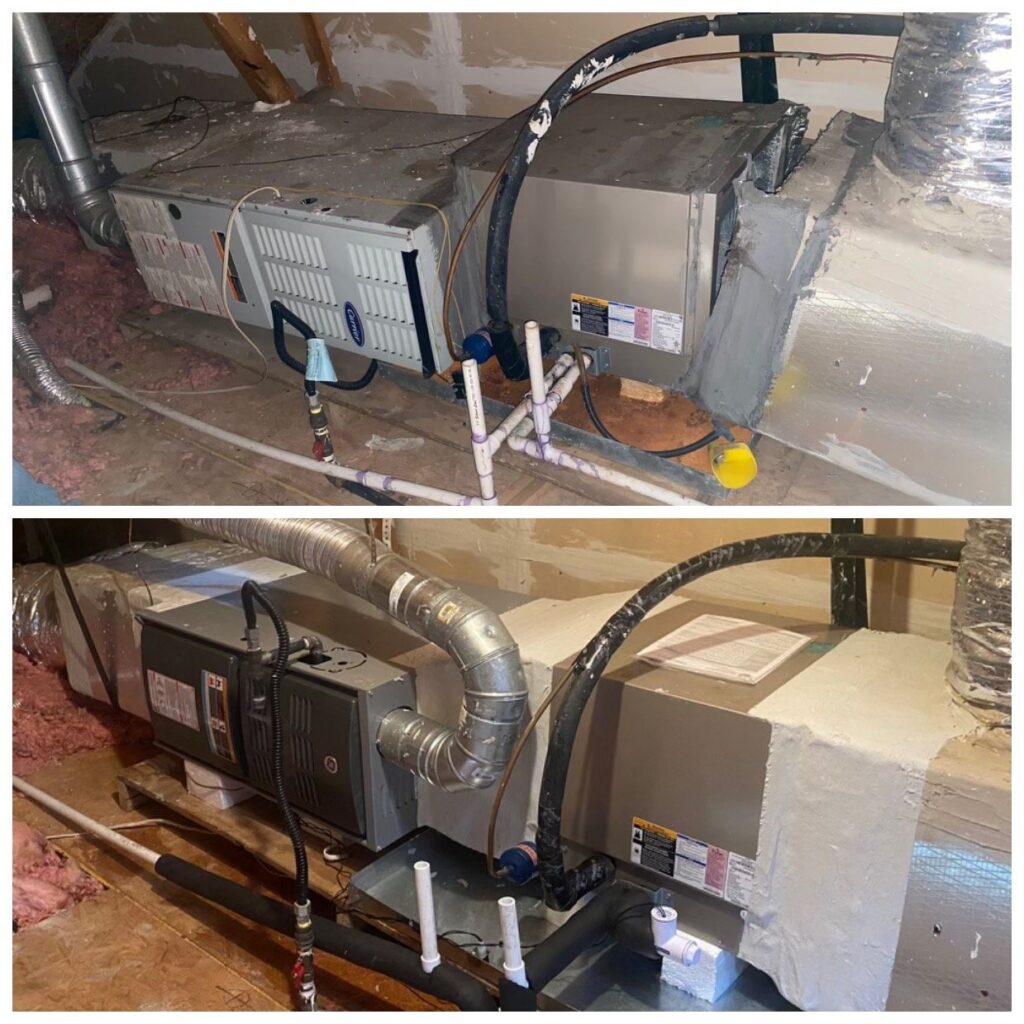
- Filter: at the grille or in a rack at the furnace's return end.
- Blower, then burners: the blower at the return end pushes air past the burners and heat exchanger.
- Coil and primary pan: in the coil cabinet, after the furnace. The primary drain leaves the coil cabinet, not the furnace.
- Secondary pan: under the coil cabinet at least, and often under both boxes (a condensing furnace needs one too), long enough to catch the coil's drips.
- Heat source: burners and a heat exchanger, vented through the flue. The burner compartment is the panel nearest the gas line and vent pipe; leave it shut, along with the vent and gas line.
Where it leaks: the coil-to-furnace seam (on the pressure side, so it blows house air out into a 130°F attic before that air even reaches the coil), the coil cabinet's access panel, the supply plenum joint, and the return joint (under suction). A coil cabinet with thin or torn insulation can sweat on its own. Rust or water marks on the furnace next to the coil cabinet, or water in the secondary pan under the seam, usually mean water got past the coil pan (or the cabinet is sweating); photograph them and let the ACR contractor confirm the source.
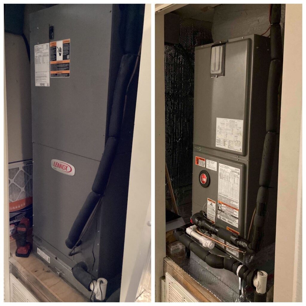
What does an upflow air handler in a closet look like?
A tall cabinet standing upright, usually on a platform or stand that doubles as the return. Air enters at the bottom and leaves through the supply plenum on top. Again: no vent pipe, no gas line.
- Filter: at a return grille in the closet wall or door, or in a slot at the base of the unit.
- Coil and primary pan: in the lower section, just above the return opening, with drain connections on the front or side.
- Blower: above the coil, pulling air up through it.
- Heat strips: at the top, near the supply outlet.
- Backup protection: because the return usually comes up through the platform under the unit, the backup here is more often a float switch (or a secondary drain line from the secondary port) than a secondary pan. Some closets do have a pan. Note which you find, or that you found neither (Module 3).
Where it leaks: the cabinet-to-platform joint and gaps in the platform (under suction, pulling air from the wall cavities or attic around the closet), cabinet seams, line-set and drain holes, and the supply plenum joint at the ceiling. Module 5 covers platform returns.
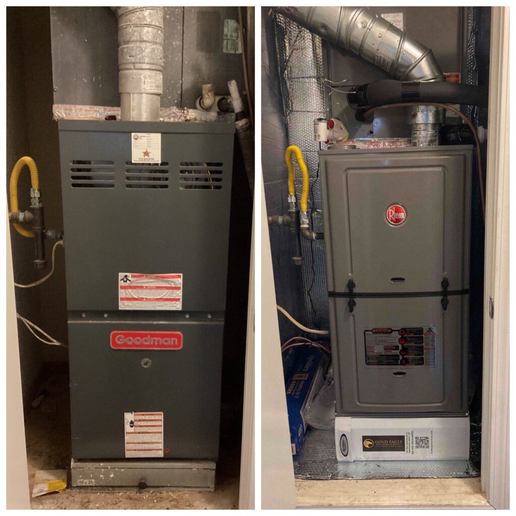
What does an upflow gas furnace with a coil on top look like?
Three stacked pieces: the furnace on the bottom, the coil cabinet on top of it, and the supply plenum above that. The vent pipe rises from the furnace beside the coil cabinet, and the gas line comes in at the side.
- Filter: at the grille, in a rack beside the furnace, or in the platform.
- Blower: in the lower compartment, behind the lower door.
- Burners and heat exchanger: in the upper compartment, behind the upper door. Never open that door.
- Coil and primary pan: in the cabinet on top, with the drain leaving the coil cabinet.
- Backup protection: as with an upflow air handler, more often a float switch or a secondary drain line at the coil cabinet than a pan under the stack. Note which you find, or that you found neither.
Where it leaks: the coil-to-furnace seam where the two boxes meet, the coil cabinet's access panel, the supply plenum joint above, and the return connection at the base. Rust streaks or water stains running down the furnace front from that seam usually mean coil or pan water is escaping; photograph them and let the ACR contractor confirm the source. Check the vent pipe for the same safety flags as on a horizontal furnace.
- Horizontal air handler: one long box, coil and pan near the return end, secondary pan under the whole cabinet.
- Horizontal furnace: two boxes in a row; the pan is in the coil cabinet, and the secondary pan runs under the coil cabinet, often under both.
- Upflow air handler: pan low, just above the return; heat strips at the top. Upflow furnace: pan up high in the coil cabinet on top.
- Return joints pull air in; supply joints, collars and the coil-to-furnace seam push it out. Rust down a furnace front points to the seam.
Photograph the plates, find the filter, look at the blower
Section 2.3 · about 4 min · then Check 2.3
Up next, after Check 2.2. Five quick questions on Section 2.2 first.
What should you photograph on the data plates?
Every data plate you can see without opening an electrical panel. The plates list model and serial numbers, which a contractor can decode for age and size. You only need sharp, readable photos: fill the frame and avoid glare.
- Air handler system: two plates, the indoor unit and the outdoor unit.
- Furnace system: three plates, two indoors (the furnace and the coil) plus the outdoor unit. The coil is its own piece of equipment with its own plate.
On a furnace, the plate is often inside the blower compartment door. Look there only with the power off (see the panel rules in 2.4), and never open the burner door to find it. Many furnace blower doors have no screws: they lift off on tabs, open with a latch, or press on a door switch. Those stay on; so does any door you can't remove under the rules in 2.4. Then write "furnace plate not accessible." A coil inside a ductboard box may have no plate you can see; write "coil plate not visible" rather than leaving a blank.
How do you check the filter location and fit?
Find the filter first; it's often not where the homeowner thinks, and some homes have filters in two places (a grille and a rack at the unit, for example).
Then check the fit. Gaps around the filter let air bypass it, carrying dust to the coil and blower, and a dirty coil holds water. Note a wrong-size filter, a bent frame, a rack with no cover, a filter installed backward (arrow pointing away from the unit), one bowed or sucked into the rack, or none at all. Photograph it in place before you pull it, lift it out gently, and put it back the same way.
Write it so the contractor can find it
"Filter rack at the air handler's return end has no cover; filter is about 1 inch narrower than the rack, leaving a gap along one side; filter face is gray and bowed toward the unit." That's three findings a contractor can act on, and none of it is a diagnosis.
What does a dirty blower wheel tell you?
A dirty blower wheel is a finding: unfiltered air has been reaching the inside of the system. On a draw-through air handler the air crosses the coil before the blower, so a caked wheel often means a dirty coil face too.
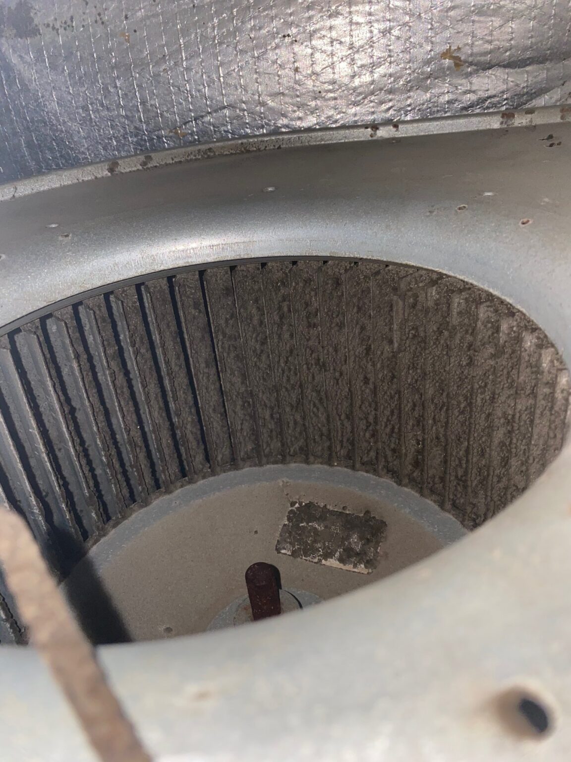
A packed wheel also moves less air, so the coil and supply air run colder and ducts and boots sweat more readily (Module 6). Photograph it with a light, with the power off, without reaching in or spinning the wheel. If the buildup looks like growth, write the wheel into your protocol like any other HVAC material (for sampling or cleaning); don't reach in for a sample during the HVAC look. Send the cause (filter bypass, a missing filter, return leaks) to the ACR contractor.
- Photograph every visible data plate: two on an air handler system, three on a furnace system (furnace, coil, outdoor unit). Write "coil plate not visible" when it isn't.
- Find the filter before you trust the homeowner's answer, photograph it in place, and note gaps, size, direction and condition.
- A dirty blower wheel means unfiltered air got inside; on a draw-through unit, suspect the coil face too.
- Photograph the wheel with the power off, without reaching in or spinning it.
With the power off, three panels are yours. The rest stay shut.
Section 2.4 · about 6 min · then Check 2.4
Up next, after Check 2.3. Five quick questions on Section 2.3 first.
Which panels can an assessor open?
With the power off at the thermostat and the service switch (Module 1), you may remove these three, to look and photograph without reaching in:
- the filter door or rack cover;
- the blower access panel, if it comes off with screws alone, with no tape, mastic or sealant over its seams, no drain or refrigerant line through it, and it isn't the electrical section. A furnace blower door that lifts off on tabs, opens with a latch or has a door switch stays on; note the furnace plate "not accessible." On many air handlers one panel covers the blower, heat strips, breakers and wiring together; that panel is the electrical compartment, so leave it on. On a furnace the blower door often shows the control board and some wiring too. That's expected: look and photograph from outside the cabinet and touch nothing. If the blower door won't come off without first removing the upper (burner) door, leave both on;
- a coil access panel held by screws alone (no tape, mastic or sealant over its seams), and only if no drain line or refrigerant line passes through it.
If tape or mastic seals a panel, leave it on and note it.
How do you tell the panels apart?
The filter door is the narrow cover at the return end. On an air handler, the electrical section is where the power wires enter the cabinet, often with breakers poking through its cover. On a furnace, the burner compartment is the one nearest the gas line and vent pipe (the upper door on an upflow furnace); the blower door is the other.
Wherever a control board or wiring is in view, look from outside the cabinet and touch nothing: the wires feeding the unit's own breaker or switch stay live even when it's off. If a panel you remove turns out to be the electrical section after all (heat strips, a breaker, or the power wires coming in), take one photo without reaching in and put it back. If you're not sure which panel it is, leave it on.
Which panels do you never open?
- The electrical or control compartment, including an air handler's heat strip section.
- A gas furnace's burner compartment (the upper door on an upflow furnace).
- Anything on the refrigerant circuit: line sets, service ports, brazed joints.
Never run the system with a panel off, and put each panel back the same way before you return the system to the state you found it (Module 1).
What is static pressure, and why should a mold assessor care?
Static pressure is how hard the blower has to push and pull against everything outside its cabinet: the filter, ducts, grilles and registers, and on a furnace system the add-on coil too. Think of breathing through a straw: the narrower the straw, the harder you work and the less air you get. Contractors measure it in inches of water column (in. w.c.) with a manometer at small test ports in the plenums. Many residential blowers are rated at 0.5 in. w.c. total external static; the data plate or manual gives the unit's own figure.
High static cuts airflow. Less air across the coil makes the coil and the supply air colder, so ducts, boots and registers sweat more, and a coil can freeze and then flood the pan as it thaws. It also changes leakage on the restricted side: a supply-side restriction pushes harder on supply seams, and a return-side one pulls harder on return seams (Module 5).
Signs you can see: a filter bowed into its rack, whistling grilles, crushed flex, few or small return grilles, and closed registers. You may also spot test ports. Plugged ones show someone measured, not that static is high, so ask for the readings. An open, unplugged port is a small leak; note it. Measuring static pressure is the ACR contractor's job: ask for the readings and the unit's rated figure for your notes. Module 5 covers it in depth.
- Power off at the thermostat and the service switch, then three panels: the filter door, a screws-only blower panel (no tape or mastic; tab, latch or door-switch furnace doors stay on) that isn't the electrical section and has no lines through it, and a screws-only coil panel with no lines through it. Look and photograph without reaching in; if a board or wiring shows, touch nothing.
- Never open the electrical or heat strip section, a furnace's burner compartment, or anything on the refrigerant circuit. Not sure? Leave it on.
- Static pressure is how hard the blower works against the filter, ducts, grilles and any add-on coil. High static cuts airflow and makes leaks and sweating worse.
- Closing vents unbalances the system and raises static pressure. The ACR contractor measures it; you note the signs and ask for the readings.
How we know this
- Equipment manufacturers' installation manuals: the blower's rated total external static (often 0.5 in. w.c.), filter placement and condensate trap requirements.
- International Residential Code (IRC) M1411.3, condensate disposal, including the secondary pan, secondary drain line or float switch required where an overflow could damage the building.
- IRC R315, carbon monoxide alarms in homes with fuel-burning appliances.
- TDLR mold rules, 16 TAC ch. 78 (what a mold assessment and its protocol cover).
Wrap-up
In a separate coil cabinet stacked on top of it
You didn't make a prediction at the top. That's fine.
A vent pipe and a gas line that both connect to the cabinet mean a gas furnace, and a furnace holds the blower and burners, not the cooling coil. The coil and its primary pan sit in their own cabinet on the supply side: on top in a closet, beside the furnace in an attic. So in this closet, the pan, its drain and the coil-to-furnace seam, one of the first joints to check, sit above the furnace. The low-in-the-cabinet answer is right for an upflow air handler, which is exactly why you name the equipment first.
Field project: your Module 2 checklist
Take it on your next job. Your checkmarks are saved on this device.
Condensate: where the water goes, and where it doesn't
Follow the drain from the pan to where it ends, and spot the failures that put water on the ceiling.
Start Module 3 →In the field (quick answer)
Every gallon an AC pulls from the air has to cross a pan, pass a trap and run downhill to a drain, a pump or the outdoors. Mold follows wherever that path fails: a clogged or sagging line, a missing or dry trap, a full secondary pan, a float switch that's missing or bypassed. Trace the path, photograph each failure point, and leave clearing and repair to a Texas-licensed ACR contractor.
By the end of this module you can:
- Find the primary pan on an air handler and on a furnace's separate coil cabinet, horizontal or upflow.
- Explain why a coil needs a trap, and spot a missing, dry or crushed one.
- Judge a condensate line's slope and trace it to where it ends.
- Read a secondary pan, secondary line, float switch and condensate pump for what they tell you.
- Tie ceiling stains, rusted pans, slime and wet return platforms to the failure behind them, and tell normal from a finding.
The water lands in a pan, and a trap lets it leave against the blower
Section 3.1 · about 8 min · then Check 3.1
Where is the primary drain pan?
The primary drain pan sits directly under the evaporator coil, so where you find it depends on the equipment. Module 2 showed the two kinds; here is why the difference matters for water.
- In an air handler, the coil and blower share one cabinet (often with electric heat strips), so the pan is built into that cabinet.
- With a gas furnace, the coil lives in its own coil cabinet: on top of the furnace in an upflow closet install, or beside it in a horizontal attic install. The pan comes with the coil, not the furnace.
Position changes the picture too. In a horizontal unit (most Central Texas attics), the unit lies on its side on a platform and the pan runs the length of the coil along the bottom. In an upflow unit (closets), it stands upright and the pan sits under the coil: in the lower part of the coil section of an air handler, or right on top of the furnace in a furnace system.
Units built to work in more than one position carry two sets of drain ports, one for each pan position. The set on the pan that sits under the coil in the unit's current position is the one in use, and the unused set should be plugged, so note any open port. In each set the secondary port sits a little higher than the primary, so it only takes water when the primary backs up. A unit lying on its side without its horizontal pan, or pitched away from its drain end, spills water past the pan; photograph any water or rust inside the cabinet outside the pan.
Which pipe is the condensate line?
Condensate lines are usually white PVC, about 3/4 inch, starting at the cabinet's drain ports. The two copper lines (the larger one wrapped in black foam) are refrigerant lines, so don't trace or touch them. Some installers wrap the drain in black foam too, so follow each pipe back to where it starts: a drain port, not a copper stub.
What about the drain on a high-efficiency furnace?
A high-efficiency (condensing) furnace, the kind with a white plastic vent pipe, also makes water, but in winter, whenever it heats. That water runs through the furnace's own trap and is mildly acidic. It is often teed into the same drain line or condensate pump as the AC coil, so one drain may carry water in both seasons. Note any corrosion below the furnace's drain connections, and remember that a shared drain that's clogged can show its symptoms in January, not just July.
Why does a coil need a trap?
A trap is a U-shaped dip in the drain line near the unit that stays full of water and forms a seal. It looks like the P-trap under a sink, but its job here is different: it lets the pan drain while the blower is pushing or pulling on the whole cabinet, pan included.
Think of a drinking straw. Put your finger over the top and the water stays in the straw; suck on it and nothing drips out the bottom. A pan under suction behaves the same way, and the trap's plug of water is what breaks that tug-of-war.
- Blower pulling air through the coil (most air handlers): the pan sits under suction. Without a trap, the blower sucks air up the drain line, and the pan holds water or spills over even when the line is perfectly clear. Water can also be pulled off the pan into the blower and blown into the supply side, so note any wet insulation or water marks just past the blower.
- Blower pushing air through the coil (a coil on a furnace, and a few air handlers): the pan sits under pressure. Without a trap, conditioned air blows out the drain, and water can sputter at the termination.
Most manufacturers call for a trap either way. Look for:
- a missing trap: the line runs straight out of the port with no dip;
- a dry trap: you can't see it from outside, but suspect it if the system sat off for weeks;
- a crushed, kinked or cracked trap, often where someone stepped on it on the platform;
- a trap packed with slime, since it's the low point where growth collects first.
Why a trap that worked last spring can fail this summer
The harder the blower pulls, the deeper the trap's water seal has to be. A clogged filter, an undersized return or a crushed return duct makes the blower pull harder, and a trap that held last year can lose its seal. That's one reason static pressure matters to a mold assessment. Measuring it is the ACR contractor's job; Module 5 covers what it means.
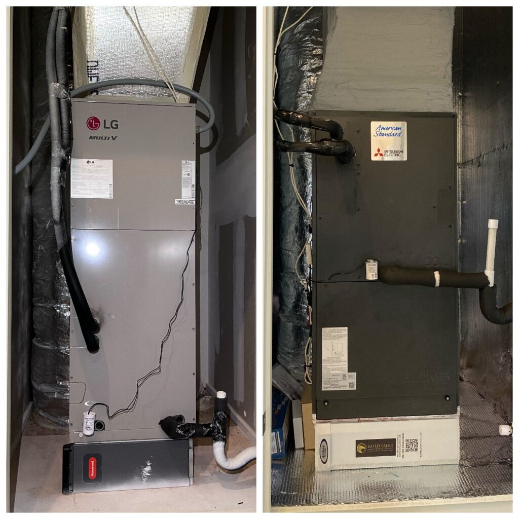
What are the short upright pipes near the unit?
They are usually a cleanout (a capped tee a contractor uses to flush the line) and a vent (an open tee that lets air in so water flows freely and the trap doesn't siphon itself dry). Where each sits relative to the trap matters, and the contractor judges whether it's right.
One placement you can spot yourself: an open tee between the unit and the trap. On most air handlers it works like a missing trap, because the blower pulls attic air in through it (dust included), and the pan can hold water or spill over. Photograph it and note which side of the trap it is on.
You can't always tell a vent from a cleanout that lost its cap, so photograph every tee, capped or open. Note standing water or slime visible in an open one, and water marks below it. Don't pull caps or probe the line.
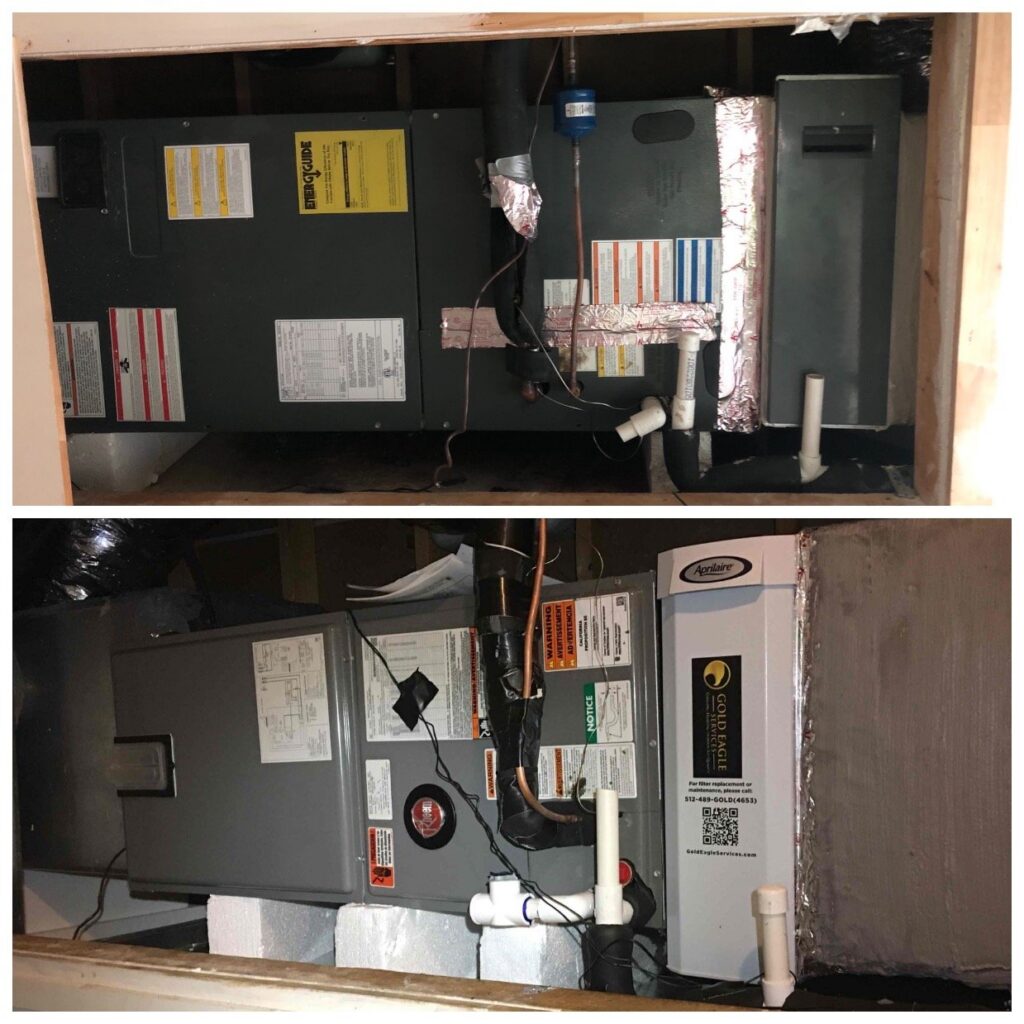
- The primary pan sits under the coil: inside an air handler, or in the separate coil cabinet of a furnace system (on top in a closet, beside it in an attic).
- Multi-position units have two sets of ports; the unused set should be plugged, and the secondary port sits higher.
- A trap's water seal lets the pan drain against the blower. Without one, a pan under suction can overflow with a clear line.
- A condensing furnace adds acidic water in winter, often into the same drain.
- Photograph every tee, trap and port, and note an open tee between the unit and the trap. Touch nothing.
Gravity is the only pump, so slope and the line's end decide everything
Section 3.2 · about 4 min · then Check 3.2
Up next, after Check 3.1. Five quick questions on Section 3.1 first. Answering questions right after you read helps it stick.
How should a condensate line slope?
The line should fall steadily away from the unit for its whole run. Codes generally call for at least 1/8 inch of fall per foot. Nothing pushes that water; gravity alone moves it, so any stretch that doesn't fall is a stretch where water waits.
A sag, where the line droops between supports or dips past a joist, holds standing water. Picture a low spot in a rain gutter: it never quite empties, and whatever grows in still water grows there. Slime builds at the low point until the line narrows or clogs. An uphill stretch, where the line climbs over a joist or a duct, does the same thing from the other side.
Sight down the line from the unit like you'd sight down a board. Note loose or missing straps, any dip and any climb, and photograph them. Don't lift, re-hang or tap the line.
Where does the condensate line end?
The primary line usually ends outdoors, at a plumbing drain, at a sink or at a condensate pump. The end of the line is called the termination, and a termination in the wrong place is a moisture source of its own. To trace it:
- Follow the pipe from the unit and note where it drops into a wall or through the soffit.
- Walk the foundation, starting near the outdoor unit (the condenser, the fan box outside), and look for a PVC stub near grade with algae or a wet slab edge below it.
- Check under nearby bathroom and laundry sinks for a small pipe tied into the drain.
- Ask the homeowner where they've seen water drip in summer.
- If you can't find it, write "termination not located." That's a finding, not a failure on your part.
Watch the termination with the system running in cooling before you shut anything off (Module 1's order of operations). A line that drips steadily on a humid afternoon is a line that's draining. A dry stub on that same afternoon is a question.
What makes a termination a finding?
- A line that keeps the slab edge or the siding above it wet, or that lets water pool against the foundation.
- A line that ends under a pier-and-beam house, putting water into the crawlspace.
- Slime or backup at a sink where the line ties in.
- A line that vanishes into a wall cavity with no visible end.
- A line that's dry while the system is running on a humid day: something upstream is holding the water. It may be a clog, a missing trap or a leak, or a coil iced over and holding the water as frost (look for frost on the large copper line or the cabinet). An iced coil sends nothing down the drain until it thaws, and then it can overflow the pan.
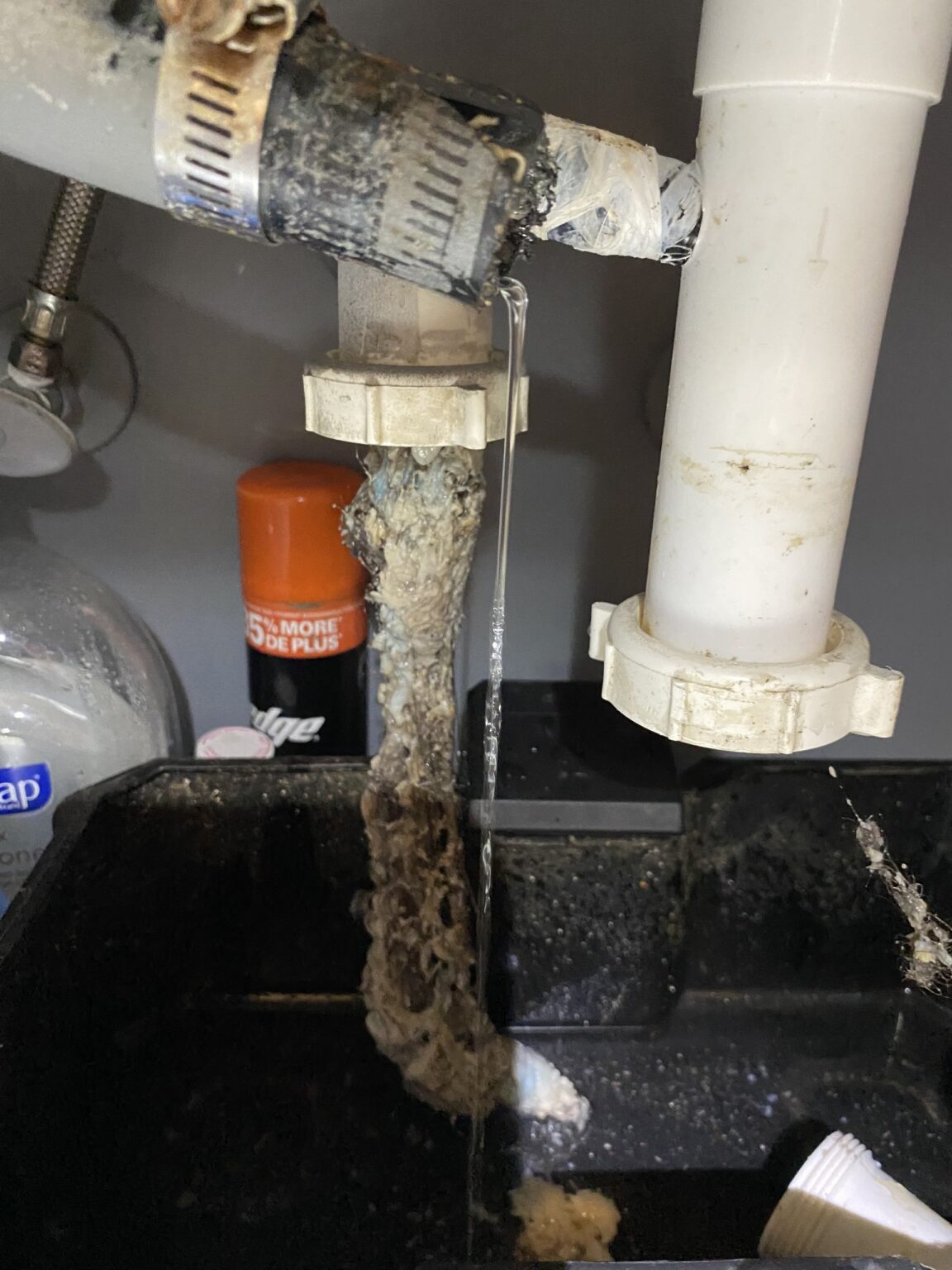
- The line should fall the whole way, generally at least 1/8 inch per foot. Sags and uphill stretches hold water and grow slime.
- Sight the line, photograph dips and loose straps, and leave it hanging as it is.
- Trace the line to its termination; if you can't find it, write "termination not located."
- Wet slab edges, crawlspace endings, slimed sinks, hidden ends and a dry line on a humid running day (a clog, a missing trap, a leak or an iced coil) are findings.
A backup only protects the ceiling if it's there and nobody has defeated it
Section 3.3 · about 6 min · then Check 3.3
Up next, after Check 3.2. Five quick questions on Section 3.2 first.
What does water in the secondary pan mean?
The secondary (auxiliary) pan is the wider, shallower pan under an attic unit, the last thing between the coil and the ceiling drywall. Think of it as a smoke detector you can see: it should stay quiet. Water in it means the primary path has already failed, or a fitting, the cabinet or the large copper line is leaking or sweating. A poorly sealed or poorly insulated cabinet in a hot attic, or the large copper line sweating where it meets the cabinet, can drip into the pan even with a perfectly clear drain. And a line that still drips at its end doesn't prove the primary path is working: a partial clog or a missing trap can still spill water past the primary pan.
Note:
- standing water, and how deep it is;
- on a dry pan, a tide line or rust ring that shows water stood there before;
- rust-through or cracks;
- a secondary line that's missing, capped or crushed;
- wet insulation or stained drywall below.
Why would a pipe over a window drip?
Residential code calls for the secondary line to end at a conspicuous point, somewhere a person will notice, which is often over a window or out a soffit. That's deliberate. So when a homeowner says "the pipe over the bedroom window drips every summer," hear a warning, not a quirk: the primary is likely blocked and water is taking the backup route.
Confirm which line it is before you write it up, because some homes run the primary there too. Then check the primary drain and the secondary pan. Also note a secondary line teed into the primary line: if the shared pipe clogs below the tee, both back up together and the backup isn't a backup.
What does a float switch do?
A float switch is a small sensor with a float that rises with water and shuts off cooling before a pan overflows. Look for it in three places: in the secondary pan, screwed into the unit's secondary drain port, or on a tee in the primary drain line near the unit.
In a secondary pan that has its own drain line, the float usually sits above that drain's opening, so it trips only if the line is blocked or can't keep up. Until then, the dripping pipe over the window is the warning.
When it trips, it usually cuts the cooling, but the blower may keep running across a wet coil and a full pan. Some switches cut power to the thermostat instead, so its display goes blank. If the system blows air but doesn't cool, or the thermostat is dead, record that; why it's happening is the contractor's call.
How can you tell a backup is missing or bypassed?
Residential code calls for a backup wherever an overflow would damage the building, which includes an attic unit above a finished ceiling. Any one of these meets it: a float switch (in the pan, on the secondary port or on the primary line), a secondary pan with its own drain line, or a secondary drain line from the unit's secondary port. Whether an install meets the code that applies is the contractor's and the city's call; your job is to record what's there. Photograph and note:
- no backup at all on an attic unit over a finished ceiling: no float switch, no drained secondary pan, no secondary line;
- a switch present but unwired, or its wires cut, twisted together or taped off;
- a switch taped, wedged or tied so its float can't rise, or lying outside the pan;
- a switch whose float sits at or above the pan's rim, so the pan would overflow before it ever tripped.
A bypassed float switch is easy to miss because nothing looks wrong. The system cools, the ceiling is clean, the homeowner is happy. It only shows itself on the day the primary clogs, when cooling keeps running, the coil keeps making water, and nothing stops it.
What goes wrong with condensate pumps?
A condensate pump is a small reservoir with a motor that lifts water where the drain can't run downhill, common in closets, garages and some attics. Most have an overflow switch meant to shut off cooling if the reservoir fills; a pump with its safety wires unused or cut has no overflow shutoff of its own.
Note water around it, a brim-full reservoir, slime, kinked or sagging tubing, and a pump that runs constantly, rattles, or hums without moving water. A pump that clicks on, empties and stops is doing its job. Don't unplug, open or tip it.
- Water in the secondary pan means the primary path failed, or a fitting, the cabinet or the large copper line is leaking or sweating.
- A dripping pipe over a window or soffit often means the primary is blocked. Confirm which line it is.
- A tripped float switch usually stops cooling; the blower may keep running, or the thermostat may go blank.
- Missing, unwired, taped or mounted-too-high float switches, and pumps with unused safety wires, are findings. A bypass shows nothing until the next clog.
Stains, rust and slime point back to the failure above them
Section 3.4 · about 7 min · then Check 3.4
Up next, after Check 3.3. Five quick questions on Section 3.3 first.
What do rust and slime tell you?
They show where water sat and where it moved, like a bathtub ring shows how full the tub got.
- Rusted pans: rust lines mark repeated standing water; rust-through means water is leaving the pan where it shouldn't.
- Slime: a slick brown or gray mat in the pan, trap or line that holds water and narrows the drain. The EPA lists poorly draining condensate pans in air handlers among the common hiding places for mold.
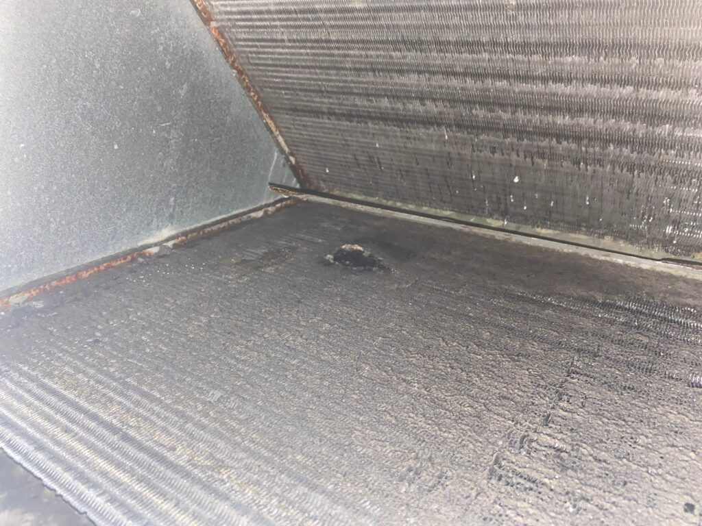
How do you read a ceiling stain against what's above it?
Stand under the stain, then go up and find what sits directly over it. The shape and the spot usually name the failure:
- Under a pan corner or under the unit: overflow, or a pan rusted through.
- Along the drain line's route: a sag or a leaking joint at the low point, or bare (uninsulated) PVC near the unit sweating, since the water inside is colder than the attic air's dew point.
- Under a condensate pump: the pump or its reservoir.
- Along the copper line set's run: the large refrigerant line sweating where its black foam is torn, missing or gapped. (Right at the cabinet, that drip usually lands in the secondary pan instead.) Photograph it; don't touch it.
Photograph from the room and from the attic so the two pictures line up, and take moisture readings on the drywall with your own meter.
Trace the drain
First follow the water from the coil to the end of the line. Then break things, one at a time or together, and see what an assessor would actually find.
After each change, scroll down for what you'd find and how to write it up.
What about water on a closet return platform?
An upflow unit in a closet often stands on a platform that doubles as the return plenum: air from the house enters the platform and rises into the blower. Overflow from the coil pan runs into that platform, and the blower then pulls return air across wet wood or drywall and sends it to every room. Look for water marks, swollen wood and rust on the cabinet base. Measure and photograph without opening the platform. Module 5 goes deeper on returns built from the house itself.
What's normal, and what's a finding?
| Normal | A finding |
|---|---|
| A wet coil and a little water in the primary pan right after a cooling cycle (seen with the power off, through a screws-only panel) | Standing water that stays long after shutdown, rust lines or slime in the primary pan |
| Steady drips at the termination on a humid day | A dry termination while running, or one that keeps the slab edge wet |
| A dry, clean secondary pan | Any water, tide line, rust ring or rust-through in the secondary pan |
| A capped tee near the unit, and an open vent tee past the trap (on the side away from the unit) | A missing, crushed or slime-packed trap, an open or uncapped tee between the unit and the trap, or an open unused drain port |
| A float switch sitting low in the pan, wired in | A float switch missing, unwired, taped, or mounted at the rim |
| A pump that clicks on, empties and stops | A pump that runs constantly, hums without pumping, or sits in water |
What do you write down, and who fixes it?
Write what you see, where it is and how much. Name the observation, not the diagnosis.
Write it like this
"Secondary pan holds about 1/2 inch of standing water; no float switch found; ceiling drywall below stained about 2 ft across; moisture meter reads [value] at the stain vs [value] at a dry reference area of the same ceiling." That beats "drain is clogged" every time.
For the drain path, write "evaluate and correct by a Texas-licensed ACR contractor," and write mold-affected HVAC materials (pans, coil, ductboard) into your protocol. Order matters: the drain should be corrected before the coil and pans are cleaned, because growth comes back on anything a broken drain keeps wet.
- Rust marks where water stood; slime marks where it moved slowly.
- Map each ceiling stain to what's above it: unit or pan corner, line route, pump, or a sweating copper line set.
- A closet return platform can pull air across overflow and send it to every room.
- A wet coil and a little water in the primary pan after a cooling cycle are normal. Water in the secondary pan never is.
- Write what you see, where and how much; the drain gets corrected before cleaning.
Wrap-up
The primary drain has likely failed, and water is taking the backup route
You didn't make a prediction at the top. That's fine.
Code puts the secondary drain line's end somewhere a person will notice, often over a window or out a soffit, precisely so a drip there gets attention. When it drips, the primary path has most likely failed and water is already on the backup route, often through a secondary pan that sits one rusted seam away from the ceiling. Confirm which line it is (some homes run the primary there too), then check the primary drain, the secondary pan and the float switch, and write down what you find.
Field project: your Module 3 checklist
Take it on your next job. Your checkmarks are saved on this device.
Ducts: ductboard, flex and the attic
Spot torn jackets, crushed flex, leaky collars and sweating boots, and learn why wet duct insulation gets replaced, not cleaned.
Start Module 4 →In the field (quick answer)
In a Central Texas attic, ducts fail at their joints: collars where flex leaves the ductboard plenum and boots where it meets the ceiling. Dirt tracks, staining, wet insulation and sweating at those joints point to air leaks and cold surfaces, and compressed, sagging, kinked or long runs starve their rooms, leaving them warm and humid with registers that can sweat. Look, photograph and take surface temperatures without stepping on or opening the ducts, tie each finding to the room it serves, and send the fix to a Texas-licensed ACR contractor.
By the end of this module you can:
- name the parts of a ductboard plenum, a flex run, a collar and a boot, and say how a good connection is built;
- read dirt tracks, staining, wet insulation and sweating as evidence of air leaks and cold surfaces;
- tell a well-installed duct system from a typical one (stretch, support, bends, length, sealing, insulation, balance) and explain why each matters for mold;
- spot and photograph crushed, sagging, kinked, long, torn and unsealed ducts, and tie each to the room it serves;
- measure ducts without damaging them, and write duct materials and causes into your protocol correctly.
An attic duct system is boxes, sleeves and joints, and the joints fail first
Section 4.1 · about 5 min · then Check 4.1
What are the ducts made of in a Central Texas attic?
Most Austin-area systems use fiberglass ductboard for the plenums and trunk boxes (the boxes that gather return air into the unit and spread supply air out to the runs) and flex duct for the runs to each room. Sheet metal plenums turn up, but they're the exception here.
Ductboard is a rigid panel of compressed fiberglass, an inch or more thick, with a foil facing outside. Installers fold it into boxes and close the seams with foil tape or mastic (a thick, paint-on sealant). The air side is porous fiberglass that holds dust and moisture, and every cut edge is raw fiberglass (seams, corners, collar holes) that passes air unless tape or mastic covers it.
Flex duct has three layers, like a sleeping bag stuffed into a raincoat:
- Inner liner (core): a thin plastic tube held round by a wire coil. This is the air channel.
- Insulation: a fiberglass blanket wrapped around the liner. Its R-value is usually printed on the jacket.
- Outer vapor jacket: a plastic sleeve, often silver or gray, that keeps humid attic air away from the cold liner.
Supply air leaves the coil near 55°F, while Austin's July dew point sits around 70°F. If attic air reaches the cold liner, it sweats like a glass of iced tea on the porch. Anything that thins the insulation (a crushing strap, a tear, a jacket pulled back) makes a cold spot, and a cold spot in a humid attic is where water shows up.
What is a collar, and what is a boot?
A collar (also called a start collar or takeoff) is the short round fitting set into a hole cut in the plenum so a flex run can attach to it. Some carry a built-in balancing damper, a plate inside with a lever outside, that the installer sets to trim the air to that room. A boot is the metal box at the other end that turns the air down through the ceiling to the register.
So every supply run has at least four joints that can leak: collar to plenum, liner to collar, liner to boot, and boot to drywall. Multiply by a dozen runs and you can see why air leaks are the biggest duct problem you'll document.
How should flex be attached at the collar and the boot?
A good connection seals the air channel first, then closes the insulation over it:
- The collar is sealed to the plenum with mastic or tape, so air can't slip around the outside of the fitting or through the raw fiberglass edge of the hole.
- The inner liner slides well onto the collar, is fastened with a tie strap or clamp, and is sealed with mastic or tape listed for ducts (printed UL 181: UL 181A for ductboard, UL 181B for flex; ordinary cloth duct tape with no UL 181 marking doesn't qualify).
- The insulation and outer jacket are pulled up over the joint all the way to the plenum and fastened with a second strap, so no bare liner or bare collar sits in attic air.
The boot end works the same way, plus one more seal: boot to drywall. You can't see the liner without pulling the jacket back, and that isn't your job. You can see whether the jacket reaches the plenum and is strapped, whether tape is lifting, whether the collar is sealed to the board, and what the surfaces around the joint look like. That's plenty.
- Plenums are usually ductboard (raw fiberglass at every cut edge); runs are flex: liner, insulation, vapor jacket.
- The jacket and insulation keep humid attic air (dew point around 70°F) off a liner carrying 55°F air. Thin insulation means a cold, sweating spot.
- Every supply run has at least four joints: collar to plenum, liner to collar, liner to boot, boot to drywall.
- A good joint is sealed (UL 181 tape or mastic), strapped, and covered by a jacket that reaches the plenum.
Air leaks leave dirt behind, and collars are where you find them
Section 4.2 · about 6 min · then Check 4.2
Up next, after Check 4.1. Five quick questions on Section 4.1 first. Answering questions right after you read helps it stick.
Why is looking around collars so important?
Because air leaks are where most duct mold problems start, and collars put the most joints in one place. A leak works differently on each side of the blower:
- A supply leak blows cold air into the attic. The room at the end of that run gets less air, and the house has to replace the air it lost, so it pulls humid outdoor air in through gaps somewhere else.
- A return leak pulls attic air into the system: hot, humid and dusty in a vented attic, humid in a spray-foam one. The system then delivers that air to every room it serves.
Module 5 covers the pressure side in depth.
What goes wrong at a collar?
Most collar failures fall into six patterns:
- Collar never sealed to the board. A hole cut too big, or no mastic or tape, leaves a ring of raw fiberglass around the fitting.
- Liner sealed with nothing but a strap. The strap holds the liner on but doesn't stop air.
- Liner pulled off the collar. A sag or a yank slides the liner off inside the jacket, and the run still looks connected. Supply air then fills the space inside the jacket, so a jacket that balloons near the plenum, a cold or damp patch there, or a starved room at the far end can be the only clues.
- Jacket slid back. The bare collar or liner sits in attic air and sweats, and the water runs onto the ductboard, platform or insulation below.
- Sharp bend right at the collar. A run that turns hard as it leaves the fitting pinches its own airway and keeps pulling on the joint until something gives.
- Tape failing in attic heat. Attic air can pass 130°F in August; cloth duct tape and some foil tapes dry out, curl and let go.
What does an air leak look like?
Dirt tracks are the signature of moving air. Fiberglass is a filter: when air pushes or pulls through a gap, it catches the dirt and leaves a gray or black line that traces the leak. Look for:
- dark rings around collars where they meet the board;
- dark lines along ductboard seams and corners, often where tape has lifted;
- dirty patches on the jacket or the insulation right at a joint;
- a dark line along the coil-to-furnace seam on a furnace system.
Read the shape. A crisp dark line that follows a seam or rings a collar says air moved there. Fuzzy, raised or spotty texture is suspect growth: document it, and sample only if your assessment plan calls for it. Wet or matted insulation under a joint points instead to a sweating surface or a condensate problem (Module 3). One joint can show all three.
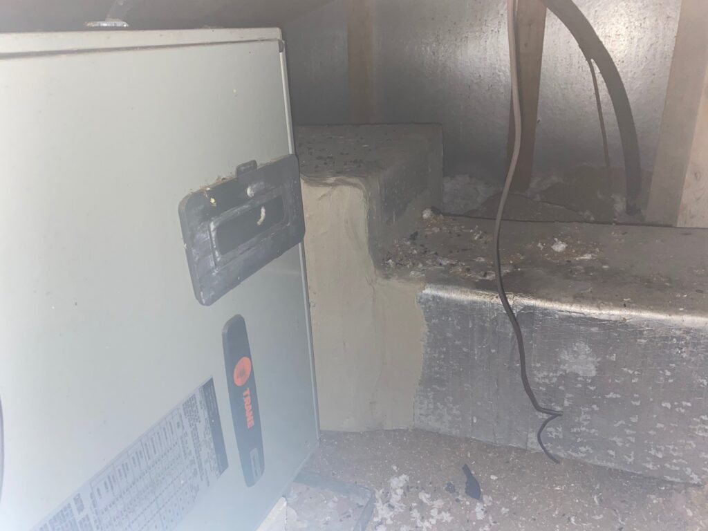
How to look at a collar
Light it from the side, not straight on: dirt lines and lifted tape edges throw shadows. Photograph the plenum wide so every collar shows, then each collar close. Number the runs the same way every time (for example, left to right as you face the plenum). Then write what you see, not what caused it: location, condition, any reading, the photo numbers, and "evaluate and correct by a Texas-licensed ACR contractor." Moving or retaping the duct yourself would hide the evidence.
Why do ceiling registers grow dark rings?
Three causes are common, and one register can show more than one:
- Soiling from the supply jet. Air leaves a register fast and hugs the ceiling, and as it moves it drags the surrounding room air, dust and all, along with it: moving air takes dirty air with it. Where that dusty air scrubs the ceiling, especially in the fast, swirling zone right at the register face, where the drywall is also cooled by the supply air, dust sticks and builds a gray ring with no moisture behind it. Dirty ducts, filter bypass and a dusty house make it worse.
- An unsealed boot. If the boot isn't sealed to the drywall, attic air can be drawn through the gap at the cutout. The drywall edge filters out its dust, which tends to leave a sharper dark line hugging the register's edge, and hot, humid attic air meeting the cold boot metal can keep that edge damp enough to grow mold.
- A roof-leak stain that happens to sit near the register.
Surface temperatures against the room's dew point, plus a look at the boot from the attic, tell which; if it looks like growth, document it and sample only if your plan calls for it. From the room, note the ring's size, rust or drip marks on the louvers and a gap at the register's edge. From the attic, look for a bare boot, a gap at the drywall and wet insulation around it.
What other damage opens a duct to attic air?
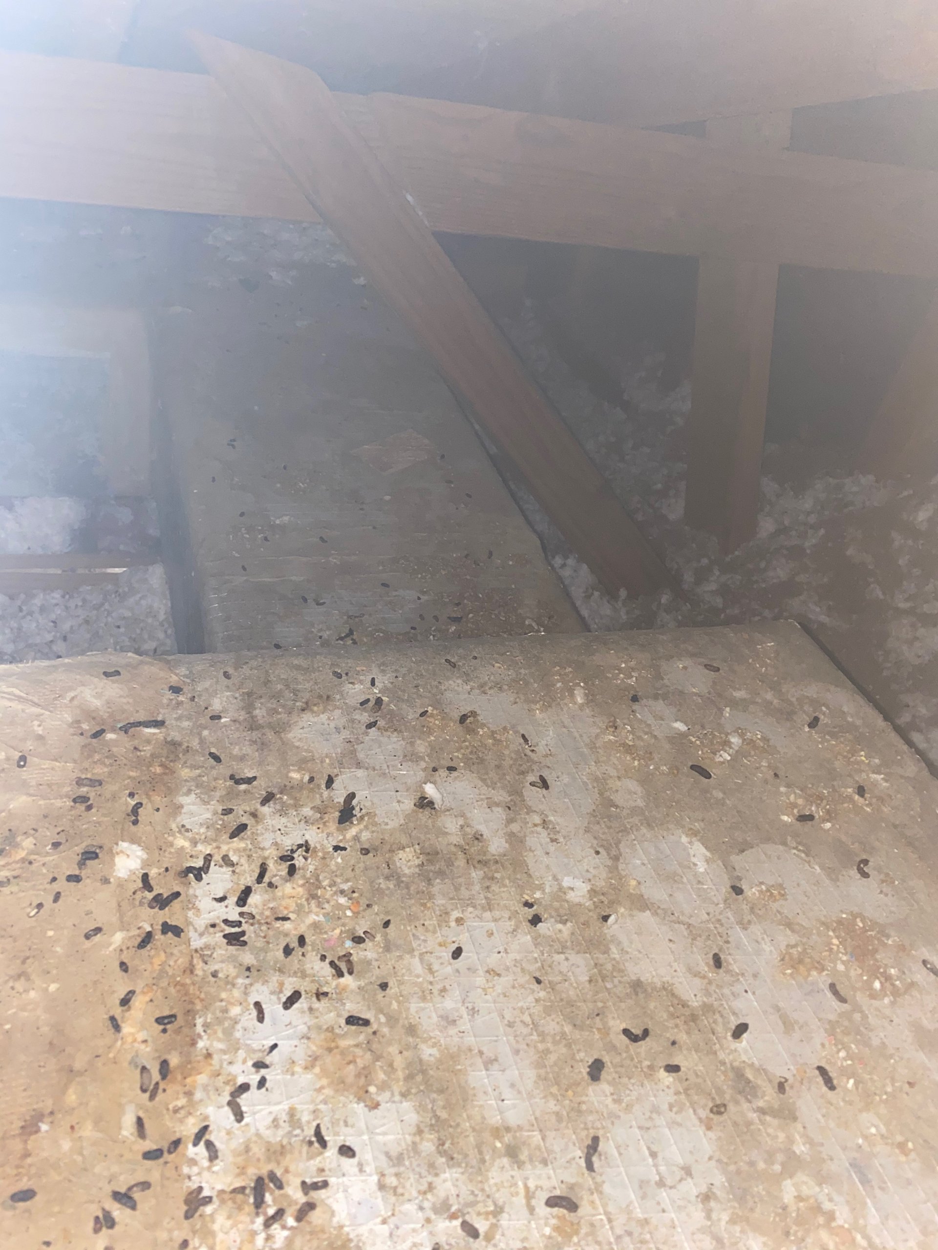
Torn jackets, tape patches over old tears, and rodent damage: chewed jackets act like tears, and nesting packs the insulation flat. Don't sweep or stir droppings.
- Supply leaks starve the room and pull outdoor air into the house; return leaks pull attic air in and deliver it everywhere.
- Collar failures: unsealed collar, strap-only liner, liner off inside the jacket, jacket slid back, sharp bend at the collar, failed tape.
- A crisp dark line along a seam or around a collar means air moved there. Fuzzy, raised or spotty texture is suspect growth.
- Register rings: dust dragged onto the ceiling by the supply jet, an unsealed boot, or a roof leak. Surface temperature vs dew point and the attic side tell which.
A good duct system is short, straight, supported and sealed. Most aren't.
Section 4.3 · about 8 min · then Check 4.3
Up next, after Check 4.2. Five quick questions on Section 4.2 first.
What does a well-installed duct system look like?
Think of each flex run as a garden hose. Laid out straight, it delivers. Coiled, kinked or stepped on, the water still comes out, but less of it, and the pump works harder. Ducts behave the same way, and the extra work shows up as higher static pressure (Module 5): more resistance for the blower, less air for the room, and more air pushed or pulled through the leaks on the restricted side.
Designing a duct system (sizing runs, choosing the layout, working out each room's air, often with ACCA's Manual D method) is the ACR contractor's job, and so is fixing one. Your job is to recognize a good installation so you can photograph where this one falls short. The flex duct industry's installation standard, from the Air Diffusion Council (ADC), gives a yardstick:
| Well designed and installed | What you often find |
|---|---|
| Flex pulled nearly tight, using only the length the run needs | Extra length left bunched or coiled; the liner squashed like an accordion |
| Supports no more than about 4 feet apart, with sag no more than about 1/2 inch per foot between them | Long sags between hangers, or no hangers at all |
| Straps or saddles at least 1-1/2 inches wide that cradle the duct | Wire or thin strap cutting into the jacket and pinching the insulation |
| Gentle bends (the curve's radius at least one duct diameter), a short straight stretch leaving each collar | Hard 90-degree turns at the collar or boot, kinks, flex folded over a joist or pipe |
| Runs as short and direct as the layout allows | Long, snaking runs to far rooms; runs crossing the attic and doubling back |
| Collars spaced out on the plenum, clear of corners and seams, each sealed | Collars crowded together or cut into a corner or seam, unsealed |
| Every seam, collar and boot sealed with UL 181 tape or mastic; boots sealed to the drywall | Cloth duct tape, curling foil tape, or nothing |
| Insulation unbroken from plenum to boot; boots insulated | Jacket short of the plenum, bare boots, torn or patched jackets |
| Enough return for the system, and each room gets the air it was designed for | One small return; far rooms starved; registers closed to "fix" it |
Why does each one matter for mold?
Compressed flex, sags, kinks and long runs. A liner that isn't stretched out folds into ridges that roughen the airway, and even modest compression adds a lot of resistance. A sag works like two bends in a row; a kink can nearly shut a run off; a long run adds resistance, joints and duct surface baking in a 130°F attic. Each one mostly starves its own room: less air arrives, and it picks up attic heat on the way, so the room stays warm and humid. A crushed or pinched spot also squeezes the insulation thin, and that stretch of jacket can drop below the attic dew point and sweat. At the register, the weak airflow no longer washes the face, so the humid room air settles on the cold louvers and they can sweat too. The far bedroom at the end of the longest, saggiest run is the classic warm, humid room with a sweating register.
Thin straps, buried ducts and ducts touching. A wire or thin strap squeezes the insulation flat where it bears, and so does a duct lying on the drywall or pressed against another duct. Each squeezed spot can become a cold spot. In a humid attic, look for a damp line under a hanger; note runs buried where you can't see them.
A hard bend at a collar or boot also strains the joint, which is how liners get pulled off.
Collar placement and too little return. Where a collar sits on the plenum affects how much air it gets, and crowded collars weaken the board and are hard to seal. A system short on return runs at high static pressure, and its return side pulls harder on every gap (Module 5). Whether a layout is right is design work: photograph the plenum wide with all its collars and let the contractor judge.
Balance. When far rooms run warm, owners close registers in the cold ones. That doesn't send the air elsewhere: it puts the system out of balance and raises static pressure, pushes more air out of duct leaks (pulling humid air into the house), and can leave the closed-off room warmer and more humid, with louvers that sweat. If a collar has a balancing damper, photograph its lever position; never move it.
Spot the flaws: one attic, seven problems
A horizontal air handler with three supply runs. Tap or click anything that looks wrong (or press Tab to move between parts and Enter to check one). Seven things here would go in your notes. Some parts are fine.
Notice that none of these flaws needs a tool to find. A flashlight, a camera and a careful look from the decking are enough.
What can you see and photograph from the decking?
Almost all of it, without touching a duct:
- Each run, collar to boot: rough length, number of bends, and the room it serves.
- Sags, with a tape held beside the duct (not resting on it) to show the drop and the hanger spacing.
- Hangers, kinks, crushed spots, ducts under walk boards or lying on the ceiling, and the jacket's R-value label if readable.
Then back it up from the rooms with your own instruments: temperature and RH in each room (the starved room usually stands out), surface temperatures at its register, and closed or blocked registers. Measuring airflow, duct leakage and static pressure is the contractor's work.
- Good flex is short, pulled nearly tight, supported no more than about 4 feet apart with wide straps, with gentle bends and sealed, insulated joints.
- Compression, sags, kinks and long runs add resistance and starve the room at the end, which stays warmer and more humid; its register can sweat, and a squeezed spot on the run can sweat in the attic.
- Thin straps, buried ducts and ducts touching each other squeeze insulation and can make cold, sweating spots.
- Closing registers puts the system out of balance and raises static pressure; it doesn't send the air elsewhere.
- Duct design (Manual D-type work) and repair belong to the ACR contractor. You photograph, tie each finding to a room, and hand it off.
Measure without harm, write ducts as remove and replace, and hand off the cause
Section 4.4 · about 5 min · then Check 4.4
Up next, after Check 4.3. Five quick questions on Section 4.3 first.
How do you measure ducts without damaging them?
Stay non-invasive. Never step on or lean on ductboard or flex; work from the joists or decking.
- Skip moisture meters on foil. A pinless meter reads foil-faced ductboard and metallized jackets badly, and pins puncture the vapor barrier you're there to evaluate.
- Take surface temperatures on jackets, collars and boots with a contact probe (shiny foil fools many infrared thermometers) and compare them with the dew point of the air around them. At or below the dew point, it's wet or about to be; a few degrees above it in still, humid air can still grow mold over time.
- Take moisture readings on the materials around the duct: the drywall around a register, the platform decking under a plenum, the framing a run rests on.
- Photograph each finding wide and close, so the contractor can find the same run.
- Don't pull jackets back, cut tape or open plenums. If the evidence is behind the jacket, write that the connection couldn't be verified without disturbing it.
If a contractor's duct leakage, airflow or static pressure readings exist, ask for them and add them to your file.
Can wet or moldy duct insulation be cleaned?
No. EPA says wet or moldy duct insulation can't be effectively cleaned and should be removed and replaced, and that no products are currently registered by EPA as biocides for use on fiberglass duct board or fiberglass-lined ducts. In practice:
- Mold-affected ductboard, flex and duct liner go in your protocol as remove and replace, not clean, spray, or coat over with a sealant or encapsulant (that last part is common remediation practice, not EPA's wording).
- Interior liner: ductboard is fiberglass inside, and some sheet metal plenums carry a glued-in fiberglass liner. EPA lists porous duct liners among the common hiding places for mold. Photograph the inside surface only where a return filter grille, or a panel you may remove with the power off under the Module 2 rules (filter door, or a screws-only blower or coil panel that isn't the electrical section and has no lines through it), already gives a view; don't cut in.
- Biocides: under 16 TAC 78.100(h) (what your protocol may specify) and 78.120(h) and 78.130(c) (what the remediator may apply), a disinfectant, biocide or antimicrobial coating goes into an HVAC system only if your protocol specifies it, it's EPA-registered for that use and applied per its label, the owner gets the safety data sheet (SDS) and agrees, and occupants are notified first. Your protocol must also weigh occupant sensitivities to the chemicals. EPA has registered none for fiberglass ductboard or lined ducts, so don't specify one for them.
- Quantities: give numbers a contractor can price, such as square feet of ductboard, length and diameter of each affected flex run, and the number of collars and boots.
Who fixes the cause, and how do you write it?
New ducts installed the same way will leak, sag and sweat the same way, so the cause has to be corrected, not just the moldy material replaced. Rerouting, supporting, resealing, redesigning and balancing are ACR contractor work. Write the finding plainly, then the handoff:
Sample report lines (made-up examples; the numbers are for illustration only)
"Supply plenum, third collar from left (serves Bedroom 2): flex jacket pulled back about 4 inches from the plenum; collar exposed; dark dirt ring at the collar-to-ductboard joint; ductboard below the collar visibly water-stained; contact surface temperature on the exposed collar 58°F, attic dew point 71°F; platform decking below reads elevated moisture. Photos 14-16. Evaluate and correct by a Texas-licensed ACR contractor."
"Supply run to Bedroom 3: estimated 35 feet with three hard bends and an 8-inch sag between hangers; section near the boot lies on the ceiling insulation. Bedroom 3 measured 77°F / 63% RH vs hallway 74°F / 55%. Duct installation and room airflow: evaluate and correct by a Texas-licensed ACR contractor."
- No moisture meters on foil. Contact-probe surface temperatures vs dew point on ducts; moisture readings on the materials around them.
- Don't pull jackets, cut tape or open plenums; write "couldn't be verified without disturbing it."
- Mold-affected ductboard, flex and liner: remove and replace. No biocides on fiberglass ductboard or lined ducts.
- The cause (leaks, sags, layout, balance) goes to a Texas-licensed ACR contractor, tied to the room it affects.
Wrap-up
In the attic: that run's collar, the run itself and its boot
You didn't make a prediction at the top. That's fine.
Start in the attic, at the duct that serves that room. A room that runs warm and humid while the rest of the house is fine points to that one run: a leaking or open collar at the plenum, a run that is long, sagging, kinked or crushed, or a boot that isn't sealed to the drywall. Each one starves the room of air. The ring itself can be an unsealed or sweating boot, or dust the fast supply jet drags onto the ceiling; temperatures and the attic side tell which. The thermostat and the outdoor unit affect the whole house, not one room. Photograph the collar, trace the run to its boot, take surface temperatures against the dew point, and hand the cause to a Texas-licensed ACR contractor.
Field project: your Module 4 checklist
Take it on your next job. Your checkmarks are saved on this device.
Air pressure and air leaks: static pressure and dirty air
Static pressure and air leaks, and how a system pulls attic and wall-cavity air into the house.
Start Module 5 →In the field (quick answer)
Static pressure is the resistance the blower works against; too little return, restrictive filters, dirty coils, restricted ducts and closed registers drive it up, which cuts airflow, makes coils and supply surfaces colder and forces more air through the duct leaks on whichever side got tighter. Return leaks, panned returns, closet platforms and closed rooms with no return path move attic, garage and wall-cavity air, with its moisture, dust and spores, through the house, and moving air leaves dust streaks and dark filtration lines that show where it has been. A mold assessor records the signs and reads or requests the contractor's readings; measuring and correcting belong to a Texas-licensed ACR contractor.
By the end of this module you can:
- explain total external static pressure, add a contractor's return and supply readings, and say why 0.5 in. w.c. is a rating, not a limit;
- tell how air handler and furnace systems read differently, and why a low reading isn't automatically good;
- name what drives static up and what high static does to airflow, surfaces, leakage and humidity;
- trace how return leaks, panned returns, closet platforms, supply leaks and closed doors move dirty, damp air;
- read dust streaks, rings and filtration lines as evidence of air movement, without over-diagnosing them.
Static pressure is the blower's blood pressure: it tells you how hard the ducts fight back
Section 5.1 · about 5 min · then Check 5.1
What is static pressure in an HVAC system?
Think of the blower as the heart and the filter, coil, ducts and grilles as the arteries. A blood pressure cuff doesn't measure how much blood moves; it measures how hard the heart pushes to move it. Narrow the arteries and the pressure climbs while the flow falls. Static pressure is that reading for an HVAC system: the resistance the blower pushes and pulls air against.
It's measured in inches of water column (in. w.c.). Residential readings run in fractions of an inch, so 0.3 and 0.8 describe very different houses.
The number that matters is total external static pressure (TESP): all the resistance outside the unit's own cabinet. Return ducts and grilles pull on one side of the blower, supply ducts and registers push back on the other, and TESP adds the two.
Is 0.5 in. w.c. a limit?
No, it's a rating. The manufacturer lists a rated external static on the data plate or in the installation manual, with a blower table showing how much air the blower moves at each static pressure. On many residential air handlers and furnaces the rated figure is 0.5 in. w.c.; the table often runs higher, and some variable-speed models list a higher maximum.
A reading above the rating doesn't mean the system is about to fail. It means the blower is fighting more resistance than it was rated for:
- A standard (fixed-speed) blower simply moves less air.
- A variable-speed blower speeds up to hold its airflow. It works harder, gets louder and pushes the pressure higher still, until it hits its own limit and the airflow falls anyway. (That is a constant-airflow motor. Some motors sold as "variable-speed," often called ECMs (electronically commutated motors), are constant-torque instead: their airflow still drops as static rises, just less than a standard blower's. You can't tell which kind from the outside, so photograph the data plate and let the contractor sort it out.)
How does a contractor measure it?
An HVAC contractor uses a manometer (a pressure gauge with probes) at small test ports drilled in the plenums: one on the return side, between the filter and the unit's cabinet, and one on the supply side, after the unit. The return reads negative (suction), the supply positive. For TESP, drop the minus sign and add: -0.30 and +0.40 make 0.70 in. w.c.
The split hints at where the resistance lives. A large return number points toward too little return or a choked filter; a large supply number toward small or crushed supply ducts or closed registers. Interpreting it is the contractor's job; yours is to read, record and request.
Why do air handlers and furnaces read differently?
In a typical air handler, the coil and blower share one cabinet, so the coil is inside the unit and already part of what the rating covers.
With a gas furnace, the coil sits in its own cabinet: on top in an upflow closet, beside the furnace in a horizontal attic install. That coil is external, so it counts against the furnace's rating and the supply reading is taken after the coil. Some contractors add a port between furnace and coil to show what the coil alone takes. The same 0.70 means something different on the two, so write down which one you're looking at. The coil-to-furnace seam sits on the pressurized side; an open one blows house air into the closet or attic before the coil can cool it.
Whose instrument is it?
Measuring static pressure, and drilling or plugging test ports, is the Texas-licensed ACR contractor's job. Your instruments stay out of the ducts. You notice the signs, read the numbers on file and request them when they're missing.
- TESP adds the return and supply readings, signs dropped.
- 0.5 in. w.c. is a common rating, not a limit. Above it, a standard blower moves less air; a variable-speed one works harder until it can't keep up.
- A low reading can hide leaks or a disconnected run.
- Air handler: coil inside the rating. Furnace: the separate coil counts against it, so the supply reading comes after the coil.
Anything that narrows the air path raises static, and high static changes where water forms and where air goes
Section 5.2 · about 5 min · then Check 5.2
Up next, after Check 5.1. Five quick questions on Section 5.1 first. Answering questions right after you read helps it stick.
What drives static pressure up?
- Too little return: too few returns, or returns too small for the system.
- Restrictive or clogged filters: a dense high-MERV filter (higher MERV catches finer dust and usually resists airflow more) on a small return, or any filter left in too long. A 4- or 5-inch media filter usually restricts less than a 1-inch filter of the same rating, so note depth as well as MERV.
- A dirty coil, dust matted on its face.
- Small, crushed or overlong ducts. A single crushed flex run mostly starves its own room; many small or restricted runs raise the supply reading for the whole system.
- Closed or blocked registers, and closed doors on rooms with no return path.
Does closing supply vents help or hurt?
It hurts, and the air doesn't just go elsewhere. Closing registers throws the system out of balance: each one adds resistance, so static rises for the whole system and the blower usually moves less air in total. Pressure in the closed branch pushes more air out of the boot and flex joints in the attic, and the coil runs colder. The closed-off room stays warmer and more humid, and a nearly closed register in a humid room can sweat on its louvers. The extra duct leakage pulls humid attic and outdoor air into the house, so closing vents adds humidity.
Count them: "4 of 11 supply registers closed at time of inspection."
What does high static do to the house?
- Less airflow, or a variable-speed blower working harder and louder to hold it.
- A colder coil and colder supply air. Supply plenums, boots and registers sit closer to or below the dew point of the air around them and sweat more readily. A starved coil can ice, stop drying the air, and flood the pan when the ice melts.
- More duct leakage on the side that got tighter. Leakage rises with pressure, so it depends on where the restriction is. A supply-side restriction (closed registers, small or crushed supply runs) pushes more conditioned air out of supply gaps. A return-side restriction (a clogged or dense filter, too little return) pulls harder, so more attic, garage or wall-cavity air comes in through return gaps.
- Filter bypass. Strong suction pulls air around a loose filter, so dust skips it and lands on the wet coil.
- Noise and comfort complaints: whistling grilles, rooms at the ends of restricted runs that never cool down.
What signs of high static can you see?
- Whistling or roaring grilles, especially returns.
- A filter sucked into its rack: bowed, collapsed, or with dust streaks around its edges where air slipped past.
- Crushed flex, closed registers, or a matted coil face (filter out, power off, as in Module 1).
Two look-alikes go on a different line. Doors that slam or drift when the system starts are a room pressure imbalance (no return path), not high static, though they often travel with restricted returns. Test ports and a contractor's sticker show someone measured, not that static is high; ask for the numbers. A port left open is a small duct leak; note it.
How do you read a contractor's readings?
From the service report, take five things: return reading, supply reading, total, rated figure, date. Add the mode and the filter's condition; readings with a dirty filter still count.
Example: return -0.45, supply +0.35, total 0.80 in. w.c., on an air handler rated 0.50. Well above the rating, so a standard blower is likely moving less air than designed (a variable-speed one is working harder), and the larger return number points toward the return side. You record it; you don't prescribe the fix. A report that only says "static OK" is a reason to request a test.
The handoff line
"Evaluate total external static pressure and airflow, and correct, by a Texas-licensed ACR contractor." Add what prompted it: "Return grille whistles; 1-inch filter bowed into rack with dust at edges; no readings on file."
- Drivers: too little return, restrictive filters, a dirty coil, restricted ducts, closed registers, closed doors with no return.
- Closing vents raises static, cuts total airflow and adds humidity. The air doesn't just go elsewhere.
- High static: less airflow, colder surfaces, more leakage on the restricted side, filter bypass. Humidity comes from leaks, starved rooms and icing, not slow air alone.
- Slamming doors and test ports are different findings from high static.
Pressure moves air through every gap, and the return side pulls from wherever it can
Section 5.3 · about 9 min · then Check 5.3
Up next, after Check 5.2. Five quick questions on Section 5.2 first.
Static pressure doesn't stay inside the ducts. Every gap on the return side is a small extra return pulling from whatever surrounds it; every gap on the supply side is a small extra supply blowing out. Try the lab first: change one thing at a time and watch the gauge, the airflow and where the dirty air comes from.
Squeeze the system and watch where the air comes from
An attic air handler (return air crosses the coil first, then the blower) serving a hallway return and a bedroom; the house has 8 supply registers and the diagram shows one, whose collar has a small leak from the start, as many do. Change one thing at a time. The gauge and numbers are what a contractor's manometer would read; the "What you could see on site" list is what you could actually see. Illustrative numbers, not a real house.
WHAT YOU COULD SEE ON SITE
How do return leaks pull dirty, damp air into a house?
A ductboard return plenum with open seams pulls attic air that can pass 130°F in August. A return or return leak in a garage pulls garage air, including vehicle exhaust (a safety finding to refer). A return box framed into a wall pulls wall-cavity air. A leak between the filter and the unit lets that air skip the filter: its dust and insulation fibers land on the entering face of the coil, where a wet coil holds them, and the rest goes out every supply in the house.
It brings Austin's moisture (the July dew point averages around 70°F), plus dust, insulation fibers, and whatever spores and fragments are in the attic or cavity. Moving air over growth can lift spores off it, so growth on a return path matters more than the same growth in a dead cavity. Look for dust trails at seams, insulation fibers on the coil face, and a return interior dirtier than the grille suggests.
A pitfall when reading reports: a return leak is an extra, easy inlet, so it lowers the suction at the test port and the blower may even move a little more air. The reading looks better while the air gets worse: less of it comes from the house through the filter, and more of it is hot, damp, unfiltered attic air. A modest return number doesn't clear an open seam with a dust trail.
What are panned returns and closet return platforms?
A panned return uses the building as the duct: a stud bay, or the space between floor joists in a pier-and-beam home, with sheet metal or ductboard nailed across one side. These cavities are rarely sealed and connect to top-plate gaps, wiring and plumbing holes, the attic or the crawlspace. Under suction, all of those feed the return.
A closet return platform is the framed box an upflow air handler or furnace sits on, serving as the return plenum. Its seams are often unsealed and can open into wall cavities or the floor, and it sits below the drain pan, so it gets both the pulled air and any overflow. In some homes the whole closet is the return, through a louvered door.
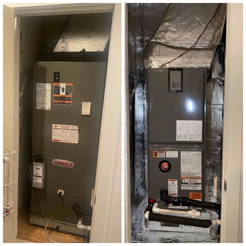
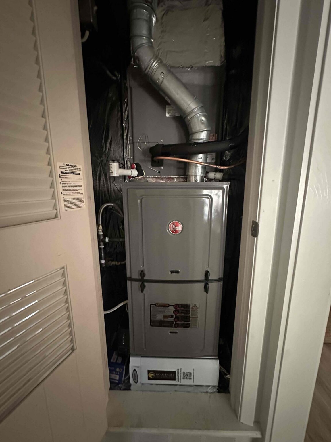
To look inside, power off as in Module 1, open the filter door and use a flashlight. Photograph raw framing, gaps into cavities, attic light, staining and visible growth. Don't cut or remove panning, tape or mastic.
How do supply leaks depressurize a house?
Supply leaks in the attic push conditioned air out while the return keeps pulling the full amount back from inside. The house runs slightly negative and makes up the difference through every crack: exterior-wall outlets, plumbing penetrations, recessed lights, the attic hatch. Hot, humid air pulled through a wall can condense on the back of drywall or under vinyl wallcovering where that surface runs below the incoming air's dew point (a room kept cool, or a wall near a cold supply). Return leaks to the attic do the opposite and push the house positive; most houses have both, and you don't need to settle which wins. A hot draft at an outlet in July tells you air is coming in, and that's what you record.
What happens in a room with no return path?
A bedroom with a supply but no return depends on the gap under its door. Close the door and the room pressurizes, pushing air out through outlets, baseboard gaps, ceiling fixtures and the undercut. The central area near the return goes negative and pulls air in from the attic, walls and outdoors. In an Austin summer, that negative side is usually the bigger moisture concern: it pulls hot, humid air toward cool surfaces.
The door-closed comparison: with the system cooling, close the door and watch whether it moves. Hold a tissue at the undercut: blowing out means the room is pressurized; pulled in means suction. The fix (transfer grille, jumper duct or dedicated return) is the contractor's call.
- Every return-side gap pulls from what's behind it, with its heat, moisture, dust and spores; past the filter, that air reaches the coil and every room unfiltered.
- A return leak can make the return reading look better while the air gets worse.
- Panned returns and closet platforms are building cavities used as ducts; inspect them power off.
- A return closet with gas equipment is a combustion-safety referral, not a code citation.
- Supply leaks push the house negative; a closed door with no return pushes the bedroom positive and the hallway negative.
The air that passes takes dirty air with it, and the marks show where air has been moving
Section 5.4 · about 5 min · then Check 5.4
Up next, after Check 5.3. Five quick questions on Section 5.3 first.
Why does moving air carry dirt from places it never came from?
A stream of air drags the still air beside it along, the way a fast river pulls water in from its banks. This is entrainment (or induction), and a supply register depends on it: its jet of cold air hugs the ceiling and pulls room air in, so the room mixes.
The room air it pulls in carries the room's dust and soot from cooking, candles, a fireplace, pets or renovation work. As the jet scrubs the ceiling, some of it sticks. That's why streaks fan out from a register: the air that passes takes dirty air with it and drops some where it touches. A damp, cold surface holds dust more readily, so the streak can be darker on a register that sweats. Moving air also scours: air rushing through a panned return or dusty plenum lifts dust, fibers and spores off the surfaces it passes.
Why do dark lines form at gaps?
The second mechanism is filtration. When air keeps squeezing through the same narrow path (carpet at a baseboard gap, a door undercut, fiberglass at a duct seam, the crack around a grille frame), the material acts as a filter, catching the dust the air carries, and the line darkens over months. Air pulled in from a dusty attic, wall cavity or crawlspace darkens it faster. A crisp line marks a long-running air path. On its own, it doesn't tell you which way the air went.
Which mechanism made which mark?
Treat this as a guide to what to check next, not a verdict.
Streaks fanning across the ceiling from a supply register
Most likely entrainment: the jet carrying room soot and dust. Darker with candles, smoking or a fireplace, and darker still if the supply air is dirty from filter bypass. Check surface temperature against the room's dew point in case the register sweats too.
A dark ring tight to the drywall edge around a register
Often the boot isn't sealed to the ceiling. Whenever the room runs slightly negative to the attic (supply leaks elsewhere, exhaust fans, or with the system off), hot attic air slips through the gap around the boot, and the drywall edge filters its dust. Where that humid air meets the cold boot it can keep the edge damp. The supply jet also drags room dust onto the same ring. Plain supply-jet dust or a roof-leak stain can look the same; the attic side and surface temperatures tell which (Module 4).
Dark lines around a return grille frame
Under the return's suction, room air pulled through the crack between frame and wall leaves its dust there, so the line marks a gap. The bigger question is behind it: if the opening isn't sealed to the return box, the return also pulls from the wall cavity or attic. With the filter out (power off), look for raw drywall edges, insulation, attic light and dust trails. A loose frame with the filter at the grille also lets air bypass the filter.
Dark lines on carpet at baseboards
Filtration through the carpet edge where air moves between the room and the gap under the baseboard. A pressurized room pushes air out there; a depressurized house can pull it in, and in a pier-and-beam home the gaps open to the crawlspace. The line doesn't tell you direction; a tissue or smoke pencil does.
A dark line under a door
Filtration at the undercut, usually on a room with no return path whose door is often closed. Run the door-closed comparison.
Look-alikes
Ceiling lines that track the framing (ghosting) come from surfaces running at different temperatures; soot darkens all of these marks. Fuzzy, raised or spotty texture is suspect growth: document it and sample only if your assessment plan calls for it.
Which non-invasive air-movement checks can you do?
Before shutting the system down for panel work (Module 1), check with the system cooling, then off at the thermostat for comparison:
- Tissue test at grille frames, return box gaps, door undercuts and outlets: it shows which way the air moves.
- Smoke pencil: more sensitive at seams and grille edges.
- Drafts: hot air at outlets or grille edges in summer means attic or outdoor air.
- Door-closed comparison on every room without a return.
Write it like this
"Dark dust line around hall return grille frame; with filter removed, drywall opening not sealed to return box, attic insulation visible. Tissue at frame pulled inward with system cooling. Evaluate and correct by a Texas-licensed ACR contractor." Mold-affected HVAC materials go into your protocol.
- Entrainment: moving air drags surrounding air and its dust along; supply jets streak ceilings with room dust.
- Filtration: air squeezing through one gap leaves a dark line that shows a path, not a direction.
- A return grille line marks a gap; look behind it for an opening into a cavity or attic.
- Causes overlap. Record the mark, the readings and the other side; the contractor diagnoses.
Wrap-up
Static pressure rose and total airflow usually fell
You didn't make a prediction at the top. That's fine.
Closing registers throws the system out of balance. Each closed register adds resistance, so static pressure rises for the whole system and the blower usually moves less air in total. The closed branches push more air out of boot and flex joints in the attic, the coil runs colder, and the closed-off rooms stay warmer and more humid. The extra duct leakage pulls humid attic and outdoor air into the house, so closing vents adds humidity. The air doesn't just go elsewhere.
Field project: your Module 5 checklist
Take it on your next job. Your checkmarks are saved on this device.
Humidity: oversized systems, fan settings and cold spots
Connect short cycling, fan ON and the leakage behind high static to high indoor humidity, and read dew point against surface temperature.
Start Module 6 →In the field (quick answer)
An AC dries a house only on long runs over a cold, wet coil, so short cycling, fan ON, duct leaks and outdoor-air ducts can leave indoor humidity high. Water condenses wherever a surface sits at or below the dew point of the air touching it, and mold can grow without drops once surface RH stays around 80% or more, so pair every surface temperature with the local dew point. Sizing, airflow and static pressure belong to a Texas-licensed ACR contractor.
By the end of this module you can:
- explain sensible and latent cooling, and why short cycling and fan ON leave a house humid;
- explain why low airflow makes surfaces colder, and how duct leaks, closed registers and outdoor-air ducts bring in humid air;
- use dew point and surface temperature to sort surfaces into dry, damp risk and condensing;
- assess vented attics, spray-foam attics and vacant houses for hidden humidity;
- write humidity findings as measurements and hand off the cause to a Texas-licensed ACR contractor.
An AC dries a house only on long runs over a cold, wet coil
Section 6.1 · about 6 min · then Check 6.1
How does an air conditioner take water out of the air?
An AC does two jobs at once. Sensible cooling lowers the air temperature, the number on the thermostat. Latent cooling removes water vapor, the difference between crisp and clammy at the same temperature. The coil does the latent job by running colder than the dew point of the air crossing it, so water condenses on the fins, drips into the primary pan and leaves through the drain. Most of a home system's capacity goes to temperature; the share that goes to water depends on how cold the coil runs, how much air crosses it and, above all, how long it keeps running.
Think of the coil as a sponge that has to fill before it drips. When the compressor starts, the coil has to get cold, then coat every fin with water before drops grow heavy enough to roll into the pan. Only water that leaves through the drain is out of the house. Water still clinging to the fins when the system stops can go right back into the air.
Why does an oversized AC leave a house cool but humid?
An oversized system cools the rooms to the setpoint so fast that it shuts off before the coil has drained much water. That's short cycling: brief runs, frequent starts. Each run spends much of its time just wetting the coil. The temperature is right, the humidity is not, and occupants call the house "cold and clammy."
Common causes: a replacement matched to the old unit's size without a new load calculation (the room-by-room estimate a contractor makes, usually ACCA Manual J), or a house that got better windows or insulation and now needs less cooling. A thermostat in a supply airstream can also cut runs short on a system sized right: the cold air satisfies it before the rooms are done. One in afternoon sun or on a warm outside wall misreads the other way (it reads warm, so runs get longer and the house is overcooled), so photograph where it sits either way.
What you can observe without diagnosing:
- Run times. If the system is cooling when you arrive, time a few cycles before you shut it down (Module 1), and note any water in the secondary pan (check the primary pan once the power is off for panel work): a float switch that trips and resets can also cause short bursts.
- Temperature against humidity. The house holds its setpoint while your hygrometer reads high RH in several rooms.
- Data plates. Photograph them. Tonnage (one ton is 12,000 BTU of heat removed per hour) comes mainly from the outdoor unit's model number; whether it fits the house takes a load calculation.
Write the observation, not the conclusion
"System ran in cycles of about 4 minutes on and 9 minutes off during the visit; indoor RH 64% at a 74°F setpoint; thermostat on a hallway wall about 3 feet from a supply register." That line is yours. "Oversized" is the contractor's word to confirm or rule out.
Why does fan ON make a humid house worse?
With the fan set to ON, the blower keeps running after the compressor stops. The coil warms, and house air streaming across it carries the water still on the fins back into the rooms: the sponge, wrung out into the house. On AUTO, the blower runs only while the system heats or cools; a long blower delay after the outdoor unit stops does the same thing on a smaller scale.
Fan ON has a second cost: the blower pulls on every return leak and outdoor-air duct the whole time, compressor or not, so humid air keeps arriving with nothing to dry it (Section 6.2). Fan ON plus a humid house is a finding worth stating plainly, with a photo of the thermostat. Changing it belongs to the homeowner or the contractor.
How do setpoints and setbacks change humidity?
The AC dries the house only while it runs. A setpoint raised for a workday or a trip lets humid air leak in with nothing removing it, and drywall, carpet and furnishings soak some up and release it for days. A very low setpoint means longer runs but colder registers and drywall. Record the setpoint, any schedule and the occupants' habits.
- Sensible cooling lowers temperature; latent cooling removes water. Water is gone only once it leaves through the drain.
- The coil has to get cold and wet before it drips, so short runs remove little water. An oversized system short-cycles and leaves the house cool but humid.
- Fan ON re-evaporates coil water into the house and keeps pulling on return leaks and outdoor-air ducts.
- Record run times, setpoint, schedule, thermostat location and fan setting; sizing is the contractor's call.
Low airflow makes surfaces colder; leaks and outdoor air make the house wetter
Section 6.2 · about 8 min · then Check 6.2
Up next, after Check 6.1. Five quick questions on Section 6.1 first. Answering questions right after you read helps it stick.
Does low airflow make the AC a worse dehumidifier?
Not by itself, and this is where many people get it backwards. When too little air crosses the coil, the coil runs colder, and a colder coil usually pulls more water out of each cubic foot of air that passes it. The humidity problems that come with low airflow come from what travels with it:
- Colder supply surfaces. Colder air leaves the coil and chills the plenum, flex runs, boots and registers. Surfaces that sat just above the dew point at normal airflow can drop below it and sweat.
- More duct leakage. The restriction raises static pressure, the resistance the blower pushes against (Module 5). A supply-side restriction pushes more air out of supply leaks; a return-side one pulls more in through return leaks.
- Starved rooms. Rooms that get little air stay warm and damp while the thermostat room is satisfied.
- An iced coil. Run cold enough, the coil freezes over, blocks its own airflow and stops drying the air at all. When it thaws after shutdown, the pan can overflow.
How do duct leaks bring humidity into the house?
Picture the house as a bottle with a few small holes. Whatever the duct system pushes out, the house has to take back in from somewhere. The direction of the leak decides the route, and both routes bring humid air:
- Supply leaks in the attic blow cooled, dried air into the attic. The house loses that air and makes it up by pulling outdoor air in through every crack, outlet and can light. In an Austin summer that air carries a dew point around 70°F.
- Return leaks in the attic pull attic air straight into the system. The coil has to remove that extra water while it runs, and with the fan ON the air reaches every room untreated between cycles. A vented attic's dew point runs roughly with the outdoor dew point, and on hot afternoons it can run a little higher as the roof deck and framing give up moisture, so it's humid air whether the attic is 95°F or 130°F.
High static makes both worse. A restriction downstream, like closed registers or crushed flex, raises the pressure in the supply ducts and pushes more air out of supply leaks. A restriction upstream, like a loaded filter or a small return, makes the return side pull harder on every gap at the collars, the plenum seams and the cabinet.
What does an outdoor-air duct or a dehumidifier change?
Look for an outdoor-air duct: a flex run from a soffit, gable or roof vent into the return plenum, often with a damper. While it's open and the blower runs, it feeds outdoor air with a dew point around 70°F straight into the system. With the fan on AUTO, most of that air crosses a cold coil. With the fan ON, it keeps coming in between cooling cycles with nothing to dry it. Note the duct, its damper or control, and the fan setting together.
A whole-home dehumidifier (a separate cabinet ducted into the system, with its own humidity control) is one more machine that makes water: note whether it runs, its setting, where its drain ends, and any water or growth around it.
What do dirty coils and blower wheels do?
Dirt cuts airflow and feeds growth at once. Dust that slips past a loose or missing filter sticks to wet fins and packs the blower wheel's blades, so the system moves less air (colder surfaces, more static) and the wet coil carries food for mold.
In an air handler, the blower and coil share one cabinet. With a gas furnace, the coil sits in its own cabinet on top or beside it, often taped shut; photograph tape and leave it, and never open a burner compartment. With the power off at the thermostat and the service switch, open only the panels Module 2 allows: a blower panel held by screws alone (tab, latch or door-switch furnace doors stay on) that isn't the electrical section and has no drain or refrigerant line through it, or a coil panel held by screws alone with no drain or refrigerant line through it. Look in and photograph without reaching in. If a panel turns out to expose wires, a circuit board, heat strips or a breaker, that's expected: touch nothing, look and photograph from outside the cabinet, and put the panel back. If you're not sure which panel it is, leave it on.
Other signs of restricted airflow: a loaded filter, crushed flex (Module 4), covered registers, a whistling return, and ice on the larger, black-insulated copper line at the indoor unit. A cold line with intact insulation and no ice is normal; bare or torn-foam spots that sweat and drip are a finding of their own, and they can stain a ceiling (Module 3). Ice can mean low airflow or a refrigerant problem; that's the contractor's call, as is measuring static pressure. Ask for any readings they have: total external static well above the data plate's rated figure means the blower is working against more resistance than it was built for.
- Low airflow makes the coil colder; the humidity comes from colder supply surfaces, more duct leakage under high static, starved rooms and an iced coil.
- Supply leaks make the house pull in outdoor air; return leaks pull attic air into the system. Both carry a dew point around 70°F in an Austin summer.
- Closed registers mean imbalance, higher static and extra humidity, never "the air just goes elsewhere."
- Outdoor-air ducts plus fan ON bring untreated humid air between cycles. Dirty coils and wheels cut airflow and feed growth.
Dew point and surface temperature decide where water lands, and mold doesn't wait for drops
Section 6.3 · about 7 min · then Check 6.3
Up next, after Check 6.2. Five quick questions on Section 6.2 first.
What is the dew point, and why does it beat RH?
Relative humidity tells you how full the air is compared with how much water it could hold at its current temperature. Change the temperature and RH changes, even though no water was added or removed. The dew point is the temperature at which that same air would be completely full, at 100% RH. It tracks the actual amount of water in the air, so it stays put when the air warms or cools. That makes it the number you can carry from room to surface.
A glass of iced tea on a summer porch shows the whole idea. The porch air isn't wet, but the glass is colder than the air's dew point, so water beads on it. Condensation forms wherever a surface sits at or below the dew point of the air touching it.
Can mold grow on a surface that never gets wet?
Yes, and this is the part most field notes miss. The thin layer of air touching a cool surface takes on that surface's temperature. Its water content stays the same, so its RH climbs. Room air at 75°F and 50% RH reads about 70% RH against a 65°F surface and about 90% against a 58°F one. That second surface never shows a drop, but the dust and paper facing on it hold moisture to match.
Call that the surface RH. Sustained surface RH around 80% or more can be enough for mold growth; the 2009 edition of ASHRAE Standard 160 set a 30-day running average of 80% surface RH as its design limit (later editions use a mold-growth model instead). So you have three zones, not two: dry, damp risk (no drops, but surface RH over about 80%), and condensing (at or below the dew point).
How does that play out at a supply register?
Supply air leaves the coil near 55°F. Take a room at 75°F:
- At 40% RH, the dew point is about 49°F. Painted drywall beside the register at 58°F sits near 72% surface RH: dry.
- At 50% RH, the dew point is about 55°F. The same 58°F drywall sits near 90% surface RH: no drops, but damp enough to grow mold if it stays that way.
- At 60% RH, the dew point is about 60°F. The same drywall is below it: condensing.
The same register can be dry in one house, quietly growing mold in a second and dripping in a third. The register didn't change. The room's humidity did, which is why Sections 6.1 and 6.2 matter as much as the register itself.
Will it sweat?
Set the air your hygrometer reads and the surface your thermometer reads. The calculator finds the dew point (Magnus formula) and the surface RH, then calls it dry, damp risk or condensing. It compares whole degrees, the way your meters read, so a surface at the dew point shown counts as condensing. Start with a preset.
Dry
How do you take readings you can defend?
- Let the hygrometer settle in each space, out of the supply airstream and sunlight, and record the dew point it calculates.
- Compare locations: the affected room, an unaffected room, outdoors and the attic. A dew point that jumps in one room points to a local moisture source.
- Don't trust infrared on shiny surfaces. Bare or polished metal (unpainted registers, foil duct jackets and foil tape) reads falsely; painted registers read fine. On shiny spots, aim at paint, use a contact probe, or read a small piece of matte tape.
- Record pairs: each surface temperature beside the local dew point, with the time and whether the system was running.
EPA advises keeping indoor RH below 60%, ideally 30-50%. Flag any surface within a few degrees of the dew point, or above about 80% surface RH, even if it's dry today.
Where does condensation show up around supply outlets?
Water gathers where the coldest air meets the most humid air. Look for beads, rusted louvers or dust in a wet pattern on registers; a stained ring on ceiling drywall; a gap between the supply boot and the drywall that lets hot attic air reach the cold boot; and a cold stripe on drywall in the airstream. A ring can also be a roof leak; paired readings with the system running show which story your notes support.
- Dew point tracks the water actually in the air; condensation forms at or below it.
- The air touching a cool surface has a higher RH than the room. Sustained surface RH around 80% or more can grow mold with no visible condensation.
- Three zones: dry, damp risk, condensing. The same register can land in any of them depending on room humidity.
- Record surface temperature and local dew point as a pair; read paint or matte tape, not shiny metal.
Attics, spray foam and empty houses: humidity with nowhere to go
Section 6.4 · about 6 min · then Check 6.4
Up next, after Check 6.3. Five quick questions on Section 6.3 first.
Why do ducts sweat in a vented attic?
A vented attic's air carries roughly the outdoor dew point, around 70°F in an Austin summer, while the ducts carry air near 55°F. Intact insulation keeps the jacket warm and dry. Sweating starts wherever attic air reaches something cold: torn flex jackets, flex squeezed flat over a joist or by a strap, gaps at the collars where flex meets the ductboard plenum, open plenum seams, and poorly wrapped boots.
Look for wet or matted insulation under runs, ceiling stains below them and drip lines on the platform. EPA says wet or moldy duct insulation can't be effectively cleaned and should be replaced; write affected flex and ductboard into your protocol that way.
Is a spray-foam attic safer for moisture?
Not necessarily, and it's arguably worse. A spray-foam (unvented) attic has foam on the underside of the roof deck and runs much closer to house temperature, so ducts there pick up less heat. But it's a closed lunchbox: humid air that gets in, from the house, from duct leaks or from a wet roof deck, has no vents to dry out through. Humidity can climb until water condenses on ducts, boots, collars and the roof deck itself; the deck is most at risk when it cools off at night.
Take the attic's temperature, RH and dew point just as you would in a room, and pair them with surface readings on duct jackets, boots and collars. For example, a spray-foam attic at 82°F and 75% RH has a dew point near 73°F, higher than a typical vented attic's. A flex jacket there at 76°F shows no drops but sits around 90% surface RH: damp risk for as long as those readings hold. Note any supply register or dehumidifier serving the attic, and whether it was running.
Same duct, two attics
In a vented attic, a sound flex jacket is hot and dry; the risk is at the tears and collars. In a spray-foam attic, the whole jacket runs cooler, and when the attic air is humid even a sound jacket can sit near the dew point, so check the run, not just the joints.
Why do vacant and closed-up houses grow mold?
A vacant house often has its cooling off or set high, so nothing removes the moisture that leaks in. Listings, estates, rentals between tenants and second homes all fit. With Austin's summer dew point around 70°F, a closed-up house can grow mold with no plumbing or roof leak: humid outdoor air seeps in, nothing dries it, and furnishings and drywall hold the moisture at high RH for weeks. It mostly takes time.
Signs: musty odor on entry, and growth on furniture, closet contents and the backs of pictures, spread through rooms rather than around one water source. Record the thermostat as found, how long the house sat empty, and whether the system runs. With the client's permission, a data logger left for a few days tells a clearer story than one visit.
What do you hand off, and how do you say it?
Hand off every question about why humidity is high and how to fix it: sizing, airflow, static pressure, routine coil and blower cleaning where there's no growth, fan and thermostat programming, duct insulation repair, outdoor-air dampers and dehumidifiers. Your report states what you measured and saw.
Mold-affected registers, boots, drywall, duct insulation, coil and blower parts go into your protocol and clearance criteria.
- Vented attic air carries a dew point around 70°F; ducts sweat where jackets tear, flex is crushed, and at collars, seams and boots.
- Spray-foam attics run cooler but can trap humidity until it condenses on ducts, boots, collars and the roof deck. Measure them like a room.
- Vacant houses with the AC off or set high can grow mold with no leak at all; a data logger tells the story.
- Write measurements and observations; "evaluate and correct by a Texas-licensed ACR contractor"; mold-affected materials go in your protocol.
Wrap-up
It can climb, because the house cools before the coil drains much water
You didn't make a prediction at the top. That's fine.
It can climb. An AC removes water only after its coil gets cold and wet enough to drip into the pan, so it dries a house on long, steady runs. A system bigger than the house needs reaches the setpoint in a few minutes and shuts off, again and again, before much water leaves through the drain. The rooms feel cold and clammy, every supply register and cold surface sits closer to the dew point, and a fan set to ON makes it worse by blowing the coil's leftover water back into the house. Whether a system is oversized is the contractor's call; your job is the run times, the readings and the cold spots.
Field project: your Module 6 checklist
Take it on your next job. Your checkmarks are saved on this device.
Writing the HVAC part of your report and protocol
The capstone: put Modules 1-6 to work on case files and write the HVAC part of your report and protocol in neutral, specific language.
Start Module 7 →In the field (quick answer)
Write each HVAC finding as five facts (location, component, condition, measurement and photo number) with no diagnosis, then add "Evaluate and correct by a Texas-licensed ACR contractor" and name no company. Put mold-affected pans, coils, ductboard, flex and liner in your protocol, with porous duct materials removed and replaced, and set clearance criteria that include confirming the cause was fixed.
By the end of this module you can:
- write HVAC findings in neutral, specific language a contractor can act on, with the system's running state beside every reading and sample;
- name the equipment correctly: air handler, or gas furnace with a separate coil cabinet;
- write mold-affected HVAC materials, containment and the system's status into your protocol, sequenced with the HVAC correction;
- set HVAC clearance criteria that match Texas rules, including how you'll confirm the cause;
- work a multi-finding case from field notes to report lines, pulling together everything from Modules 1-6.
A finding is five facts and a handoff, never a diagnosis
Section 7.1 · about 12 min · then Check 7.1
How do you write an HVAC finding in a mold report?
Write what you saw, where, how much, and which photo shows it; leave out why it happened. Every good HVAC finding line carries five facts:
- Location: attic, hall closet, garage; which unit if there are two.
- Component: primary drain pan, return plenum, supply boot in bedroom 2.
- Condition: what's visible: standing water, rust, dark staining, a gap, dust lines.
- Measurement: depth, length, count, surface temperature, RH, moisture reading, with the time, the instrument, and whether the system was running.
- Photo: the number in your photo log.
"AC has mold" sends a contractor to the attic guessing. "Visible suspect growth on the face of the primary drain pan, horizontal air handler, attic, about 4 by 10 in (photos 7-9)" sends them to the right cabinet with the right parts in mind.
The running state belongs on every reading, and on every air sample. A sample taken with the blower moving the house's air through a dirty system and one taken with it off are not the same test, so record the system state, the fan setting (AUTO or ON) and the time beside each one. Without that, nobody can compare your before and after results.
When may you change the system? Only after you've recorded it exactly as you found it: mode, setpoint, fan setting, running or not, and the time. After that, two kinds of change are part of your job, as long as each one goes in your notes with the time: setting the thermostat or fan for a planned comparison reading or sample, and turning the power off at the thermostat and the service switch before you lift a screws-only access panel (Modules 1 and 2). Sliding the filter out at its filter door to read its size and photograph it, then putting the same filter back, is also fine; replacing it is not. Put it back the way you found it when you leave. Adjusting or repairing is not your job: opening closed registers, swapping the filter, clearing a drain, resetting a float switch or cutting tape off a panel changes the evidence. Record it and hand it off.
What words should you avoid in HVAC findings?
Avoid any word that names a cause or a repair; those are the ACR contractor's call. You saw water in a pan. You didn't see the clog.
| Write | Instead of |
|---|---|
| Primary pan holds about 1/2 in of standing water; secondary line dripping at the soffit | Drain line is clogged |
| Dark dust lines on the ductboard around 3 of 5 return collars; no mastic visible | Ducts are leaking |
| COOL, setpoint 74°F; three cycles timed at about 4 min on, 9 min off; indoor RH 64% at 2:10 p.m. | System is oversized |
| Visible suspect growth on the coil face, viewed through the coil access panel | Black mold on the coil |
| One 20 by 20 in return grille serves the whole system (photo 3) | Bad duct design |
"Black mold" is worth dropping for its own reason: EPA notes it isn't a species, and the phrase reads like a conclusion you haven't drawn.
How do you name the equipment correctly?
Call it an air handler when the blower and coil share one cabinet, and a gas furnace with a separate coil cabinet when they don't. The contractor needs to know which before climbing the ladder. A furnace system has a vent pipe and a gas line, and its coil sits in its own cabinet: on top in an upflow closet install, beside the furnace in a horizontal attic install.
The difference changes your report in three places:
- Data plates: an air handler has one main indoor plate (a heat-strip kit inside it may carry its own label); a furnace system has two main plates, one on the furnace and one on the coil cabinet. Both have the outdoor unit's plate too. Photograph every plate and label you can see; the vent pipe and gas line, not the label count, are what tell you it's a furnace.
- Seams: the joint between the furnace and the coil cabinet is a finding location an air handler doesn't have.
- Where the growth is: "coil cabinet above the furnace" and "air handler, coil section" point to different panels.
What photos does the contractor need?
A wide shot that shows where each part sits and a close shot that shows its condition, for six things: data plates (indoor and outdoor, model and serial numbers readable), pans (with a tape measure in frame), drain terminations and any float switch, collars, plenum seams (including the coil-to-furnace seam), and the filter rack with the filter's printed size. Add the thermostat as you found it, and number every photo to match your finding lines.
What should the handoff line say?
One fixed line after each finding that needs a fix: "Evaluate and correct by a Texas-licensed ACR contractor." Name no company.
Texas law bars doing both assessment and remediation on the same project (Occupations Code 1958.155). Naming an ACR contractor isn't forbidden, but many HVAC companies also hold mold remediation licenses, so a name can steer the owner to a company with a stake in the remediation, and TDLR's code of ethics (16 TAC 78.72) asks you to avoid and disclose conflicts of interest. A neutral line keeps you clear.
Keep the handoff as narrow as the finding: "the condensate drain system," "the return plenum connections," "static pressure and airflow." "Full system replacement recommended" is a diagnosis. For static pressure, you write the visible signs (a bowed filter, closed registers, kinked flex, a roaring return) and request the test: "Recommend static pressure and airflow evaluation, and correction, by a Texas-licensed ACR contractor." The contractor measures it with a manometer; you don't.
The test for every line
Could a contractor who has never seen the house walk to the right part, know what you saw, and check your number? If yes, it's a finding. If it tells them what's wrong or how to fix it, cut that part.
- Five facts: location, component, condition, measurement (with time, instrument, running state), photo number.
- No cause or repair words: no "clogged," "leaking," "failed," "oversized," "undersized" or "black mold."
- Air handler (one cabinet) or gas furnace with a separate coil cabinet (vent pipe and gas line, two main plates, one more seam).
- "Evaluate and correct by a Texas-licensed ACR contractor," scoped narrowly, no company named. You note static signs; the contractor measures.
The protocol takes the growth; the ACR contractor takes the cause
Section 7.2 · about 9 min · then Check 7.2
Up next, after Check 7.1. Five quick questions on Section 7.1 first. Answering questions right after you read helps it stick.
How do you write mold-affected HVAC materials into the protocol?
Treat mold-affected HVAC parts like any other affected material: list them by location, quantity and method in your written work analysis (the remediation protocol). The client gets it at least one calendar day before remediation starts, and it covers areas, quantities, methods, PPE, containment, clearance criteria and how you'll decide whether the underlying cause has been remediated (Occupations Code 1958.151; 16 TAC 78.100).
Split the materials in two:
- Non-porous: metal or plastic drain pans, coil fins and cabinet walls, sheet metal collars and boots, metal registers. The method is removing the growth (for example HEPA vacuuming and damp wiping, and cleaning the coil in place), not spraying alone. A pan rusted through, or a coil too corroded or packed to clean, may need replacement instead; say which.
- Porous: fiberglass ductboard; flex duct, whose insulation is porous (replaced whole, liner included); and a bare fiberglass cabinet liner. Liners vary, and a foil-faced or foam liner is a different case, so describe what you saw. EPA says wet or moldy duct insulation can't be effectively cleaned and should be removed and replaced. Applying that to a cabinet liner is your professional call; note how you decided.
Give quantities a contractor can price: square feet of ductboard, linear feet and diameter of each flex run, number of boots and collars. The totals also help decide whether the project reaches 25 contiguous square feet, which brings in licensed remediation, TDLR notification and containment. Whether duct surface counts toward it is a question to check with TDLR.
Write in a check of the surfaces under or behind any removed ductboard, flex or liner (framing, decking, drywall, cabinet walls) before new materials cover them. That may mean a mid-job visit.
Can the protocol call for a biocide in the HVAC system?
Only on Texas's terms (16 TAC 78.100(h), 78.120 and 78.130): your protocol specifies it, it's EPA-registered for that use, it's applied per its label, the owner gets the safety data sheet and agrees, and occupants are notified first. EPA notes no biocides or antimicrobials are registered for use on fiberglass ductboard or fiberglass-lined ducts, so a spray never stands in for removing porous duct materials.
What happens to the system during the work?
State that the system serving the work area stays off, or its supply and return openings in the work area stay sealed, from setup until clearance; that the filter is replaced before it runs again; and whether ducts that ran during removal need cleaning. A system run during demolition can carry disturbed growth through the house. Inside walk-in containment, Texas rules require supply and return vents to be blocked and the containment kept at negative pressure, lower than the areas next to it (16 TAC 78.120).
Who does which part?
In many units the primary pan is built into the coil assembly, and replacing a coil opens the refrigerant circuit, which needs a Texas-licensed ACR contractor working with the remediator. TDLR's HVAC mold rule (16 TAC 78.130) notes that ACR contracting requires a TDLR ACR license, which is why the handoff line names it. Write the scope, not the company.
Texas law (Occupations Code 1958.002(b)) says the mold law doesn't cover the diagnosis, repair, cleaning or replacement of HVAC or air duct systems when it isn't done for mold assessment or remediation. This course reads that to mean removing mold from HVAC parts stays under ch. 1958 and the remediator's license; confirm that reading with TDLR.
Should the HVAC fix come before or with remediation?
Correct the moisture or air-leak cause before or alongside remediation, or the growth comes back. New flex on a return collar that still pulls attic air puts you back in the same attic within a season.
A common order
- The ACR contractor restores the condensate drain before the coil and pan are cleaned, because cleaning puts water in the pan.
- The remediator removes affected ductboard, flex and liner, then cleans the coil and pan in place, so tear-out debris doesn't land on parts that were just cleaned.
- You check the exposed surfaces (the mid-job visit).
- The ACR contractor installs and seals the new ducts before the system restarts.
Write it in plain words: "Remediation of HVAC components to be coordinated with correction of the condensate drain system by a Texas-licensed ACR contractor."
- Work analysis: at least one calendar day before; areas, quantities, methods, PPE, containment, clearance criteria, how you'll judge the cause.
- Non-porous: remove the growth (not spray alone). Porous ductboard, flex and bare liner: remove and replace, with quantities.
- System off or work-area openings sealed until clearance; containment vents blocked, negative pressure; new filter before restart.
- Fix the cause before or with remediation: drain first; porous materials out, then coil and pan cleaned; new ducts sealed before restart.
Clearance is your call, and it includes the cause
Section 7.3 · about 8 min · then Check 7.3
Up next, after Check 7.2. Five quick questions on Section 7.2 first.
What does it take to pass HVAC clearance?
HVAC clearance is your post-remediation assessment as the licensed mold assessment consultant, using the visual, procedural and analytical methods your protocol specified (16 TAC 78.100 and 78.140). To pass, you confirm that:
- the work area is free of all visible mold and wood rot;
- the work was done according to your protocol and the remediator's work plan;
- the results meet the clearance criteria your protocol set;
- to the extent feasible, the underlying cause was remediated, so it's reasonably certain the mold won't return from that cause.
The clearance statement comes from you, not the remediator. On a licensed project, your protocol names at least one nationally recognized analytical method for each remediated area and the criteria for judging results. Where it calls for walk-in containment, you assess while the containment is still up. To change a method, document the change in writing and get the client's approval first. EPA notes there are no federal limits for mold or spores in indoor air, so the criteria you write carry the weight.
Think of it like a roof inspection after a storm repair: new shingles that look perfect don't pass if the flashing that let the water in was never touched. A clean pan over the same sagging drain line is the same story.
What does an HVAC clearance inspection cover?
- Pans and coil: viewed through access panels removed with the power off, or opened by the ACR contractor if taped or sealed; no visible growth.
- Removed porous materials: the surfaces under or behind them checked before new materials covered them; then the new ductboard and flex confirmed in place where the protocol called for them.
- Collars, seams and boots in the work area: no visible growth.
- The system: still off, or its work-area openings still sealed, with a new filter ready before restart.
- Your samples: each one recorded with whether the system and blower were running and the fan setting, matching how your protocol said it would be done.
How do you confirm the cause was corrected?
With paper, not promises. Your file should hold:
- the contractor's written findings and what they corrected;
- static pressure readings (total external static, in. w.c.) before and after, beside the unit's rated figure from the data plate or manual. Typical air handler and furnace blowers are often rated at 0.5 in. w.c., but check the data plate or manual. A made-up example of how it reads: "before: return -0.38, supply +0.42, total 0.80 on a unit rated 0.50" means the blower was working against far more resistance than it was built for; the after reading shows what changed;
- photos of the corrected items: drain flowing at its termination, float switch in place, collars sealed with mastic;
- your own repeat readings where the cause was humidity: RH, dew point and surface temperatures at a comparable time of day, with the system state.
You read the static numbers; you don't take them. Together these support your determination on the cause, which is what the cause box on the Certificate of Mold Damage Remediation records (Occupations Code 1958.154).
What goes on the limits list?
A plain list of what you couldn't see: the inside of long flex runs, the inner rows of a coil, a taped or sealed cabinet, a collar buried under insulation. It tells the next reader exactly where your determination stops.
- Four tests: no visible mold or wood rot, work per protocol and work plan, criteria met, cause remediated as far as feasible.
- Your call, by your protocol's analytical method for each area; assess before walk-in containment comes down.
- Cause file: contractor's written findings, static before and after vs the rating, photos, your repeat humidity readings.
- List the limits: what you couldn't see.
Four case files: the whole course, one house at a time
Section 7.4 · about 18 min · then Check 7.4
Up next, after Check 7.3. Five quick questions on Section 7.3 first.
Real jobs rarely hand you one finding. Each case stacks two or three from different modules; the skill is keeping them apart: one line per finding, the cause to the contractor, the growth to your protocol. These houses and every reading in them are made-up teaching examples, not real job data.
Case A: Attic air handler, sagging primary line, stained ceiling
- On arrival: COOL, 74°F, fan AUTO, running. Filter at the hall return grille bowed inward; flex to bedroom 2 kinked over a joist; return grille loud.
- Hall ceiling: stain about 18 by 24 in, directly under the condensate line's route, not under the unit.
- Attic: horizontal air handler, no vent pipe or gas line. Primary line sags about 1-1/2 in between two straps; drip marks on the joist under the low point; insulation below damp and matted. You switch the unit off at the thermostat and the service switch at 10:25 a.m. and note it; through the screws-only access panel, the primary pan holds about 3/4 in of water at 10:40, with dark slime on its floor. Secondary pan dry, float switch present in it.
What it ties together: the stain maps to the line, not the pan (Module 3), which is why the float switch in the secondary pan never tripped: the water left the line downstream of the pans (a leak, or a cold line sweating at its low point; which one is the contractor's call), so none of it reached the secondary pan. The bowed filter, kinked flex and loud return are signs of high static pressure (Module 5), which you note and hand off. Two findings, two handoffs: "the condensate drain system" and "static pressure and airflow." The slime in the pan goes in your protocol as a cleaning item, after the drain is restored.
Build the finding: Case A's drain line and ceiling
Pick one phrase for each of the six parts (all readings are made-up examples). Your report line builds as you go, beside the drawing on a wide screen and in the bar at the bottom of this figure on a phone. Vague choices get a dotted underline; wrong, missing, diagnosis, out-of-scope and company-naming choices get a wavy one.
Notice that the best line never says why the water left the line. The sag, the drip marks and the stain are enough for a contractor to find it.
Case B: Closet furnace, panned return, dust lines
- The equipment: upflow gas furnace with a metal vent pipe and a separate coil cabinet on top: two indoor data plates. Rust streaks on the furnace panel just below the coil cabinet. The coil cabinet panel is taped shut.
- The return: the furnace sits on a framed return platform, grille in its face. With the power off and the filter out, a flashlight shows raw drywall seams with gaps into the wall cavity and dark suspect growth on the back of the drywall.
- Dust lines: dark lines on the carpet at the closet door and the hall baseboards; dark streaks at the platform seams; a tissue at one gap pulled in hard while the system ran. The coil-to-furnace seam is unsealed, with dust streaks.
What it ties together: this is dirty air pulled in through leaks. The return's suction pulls wall-cavity air, with its dust and fibers, in through every open seam and gap in the platform, and the tissue shows it (Module 5). Those gaps sit past the filter, so that air reaches the coil and blower unfiltered. Wherever air keeps squeezing through the same narrow path, at the platform seams, under the closet door or along a baseboard, the carpet or seam edge filters its dust out. The dark lines are those filtration lines (Module 5): they mark where air keeps passing, though a line alone doesn't tell you which way it went. Name the equipment right (Module 2): "coil cabinet above the furnace," with the taped panel left taped and put on your limits list. The rust streaks point up to the coil pan (Module 3). A return in the same closet as a gas furnace is a combustion-safety item: note it and refer it promptly, without calling it a code violation. Protocol: the platform's growth-affected drywall lining, removed and replaced, in square feet; the open seams to the contractor.
Case C: Vacant house, short cycles, sweating registers
- As found: house listed for sale and empty for about three months (per the agent). COOL, 72°F, fan ON. Three cycles timed at about 4 min on, 10 min off. Musty odor; suspect growth on closet contents in several rooms, not clustered at one water source.
- Readings: 73°F and 66% RH in the main bedroom, dew point about 61°F. Register louvers there 58°F by contact probe, with beads of water; rings of suspect growth on the drywall around 4 of 9 supply registers. 3 of 9 registers closed.
- Attic: two boots not sealed to the drywall; flex to the main bedroom kinked.
What it ties together: three humidity drivers on one thermostat (Module 6): short cycles, fan ON returning coil water to the house, and an empty house with no people, cooking or showers adding heat, so the system runs less while humid outdoor air keeps seeping in. The closed registers aren't sending air elsewhere; they unbalance the system, raise static pressure and bring extra humidity (Module 5). The louvers sit below the room's dew point, so they sweat (Module 6), and the unsealed boots let attic air reach cold metal (Module 4). Your line uses the run times, never "oversized." Because the fan was ON, the blower ran through your whole visit, so every air sample gets "COOL 72°F, cycling about 4 min on / 10 min off, fan ON, blower running continuously" beside it. You don't change the settings to make the results look typical; if you switch the fan for a planned comparison sample, write down what you changed and when, and set it back. Handoffs: the system's cycling, airflow and humidity control; and the supply boot connections at the ceiling (two boots not sealed to the drywall).
Case D: Spray-foam attic, high RH
- Attic, 10 a.m.: foam on the underside of the roof deck, no vents. 80°F, 72% RH, dew point about 70°F.
- Supply side: jackets slid back about 3 in at two supply collars; exposed metal collars 60°F by contact probe, beaded with water; dark suspect growth on the ductboard facing below them, about 6 by 10 in each.
- Return side: dark dust lines along two return plenum seams.
What it ties together: a foam attic runs near house temperature, but with no vents to dry it, humidity can climb until its dew point is high enough to condense on collars, boots and ducts (Modules 1 and 6). Cold collars at 60°F in 70°F-dew-point air sweat (Modules 4 and 6). The return seam lines are filtration lines again: the return's suction pulls the attic's humid air in through those seams, past the filter, the seam edges catch some of its dust, and the system delivers the rest of that air to every room (Module 5). Protocol: the affected ductboard, in square feet, and the flex runs at those collars if their insulation is wet or growth-affected, by linear feet and diameter, removed and replaced; the surfaces behind checked before new materials go in. Handoff: "Evaluate and correct the supply collar connections, return plenum seams and attic humidity by a Texas-licensed ACR contractor." The attic's humidity gets its own mention because the collars sweat only when the attic air is that wet; a spray-foam attic with no vents has nothing to dry it, which makes it arguably a bigger moisture risk than a vented one. Clearance: the contractor's photos of sealed collars and seams, plus your own attic temperature, RH and collar temperatures at a comparable time of day.
- One line per finding; map each finding to its own cause and handoff.
- A stain under the line's route is not a pan overflow, and a float switch in the secondary pan can't catch it.
- Dirty air pulled in through leaks: return suction draws cavity or attic air in through open seams and gaps, and the dust lines where it keeps squeezing through are filtration lines (Module 5).
- Record the running state and fan setting with every reading and sample, and any change you make (for a comparison sample, or power off for a panel) with its time; write run times, not "oversized."
Wrap-up
Not yet. I still need to confirm the cause was fixed.
You didn't make a prediction at the top. That's fine.
Not yet. No visible mold is only one of four things you confirm at clearance. The other three: the work followed your protocol, the results meet the criteria you wrote, and, as far as feasible, the underlying cause was remediated. A clean pan over the same sagging drain line will grow again. The contractor's written findings and photos of the corrected items (a drain flowing at its termination, the line re-sloped and strapped), plus static readings before and after where airflow was part of the cause, are what let you sign off on the cause. The statement is yours, not the remediator's.
Field project: your Module 7 checklist
Take it on your next job. Your checkmarks are saved on this device.
GES 101 · HVAC Awareness for Mold Assessment Consultants · goldeagleservices.com/pro-training
Finish the course
Here's where you stand across all 7 modules.